This thread has been locked.

If you have a related question, please click the "Ask a related question" button in the top right corner. The newly created question will be automatically linked to this question.

TMS320C6672: Simplest Way To Boot an Application From NOR Flash Through EMIF16

Part Number: TMS320C6672

Hi, I've been working on a C6672 DSP and trying to find a way to boot it with an application image for months now. I'm able to download and debug applications on both cores using the XDS560 emulator, but still hardly have any idea on how the bootloading process is supposed to work.

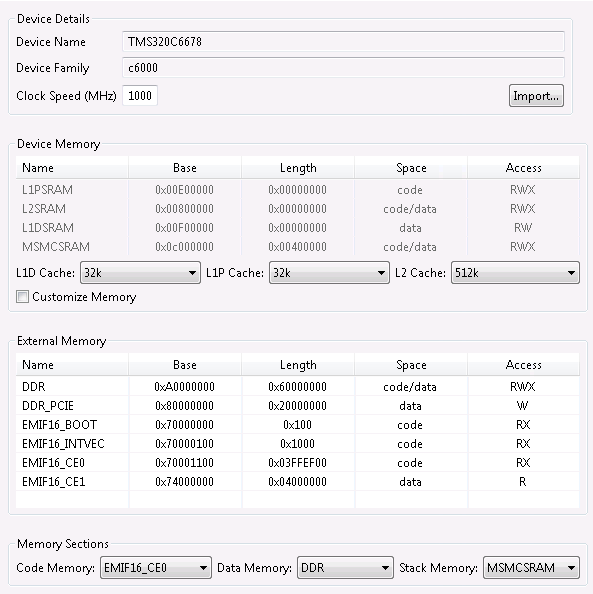
I have a 128-MB NOR flash connected to the DSP through the EMIF16 interface (in the address range 0x7000000:0x77FFFFFF), and I want to convert my application.out file to a bootable *.bin file so that the DSP autonomously boots with that application image flashed onto NOR.

I've referred to the following wiki pages and forum posts:

http://software-dl.ti.com/processor-sdk-rtos/esd/docs/latest/rtos/index_Foundational_Components.html#c66x

https://e2e.ti.com/support/processors/f/791/t/367102

To my understanding, the bootloading process works as follows (please verify my in case I'm mistaken):

  • The DSP has an internal boot ROM (at 0x20B00000:0x20B1FFFF) consisting of the ROM Bootloader (RBL).
  • When reset, DSP uses the RBL (regardless of the boot pins), and then, the RBL checks the boot pins and transfers control to the Intermediate Bootloader (IBL), which is located on the EEPROM connected via I2C (on slave address 0x51).
  • The IBL then finds the bootable *.bin file on the NOR flash and transfers it the control over the processor.

What's confusing to me is:

  • Given the boot pins are set to I2C master boot with slave address 0x51, how does the IBL know where the application image is located? I mean, in this example, the IBL transfers control to the application binary located in the NOR flash, but how does it know the application is in NOR flash and in which address range the application is flashed?
  • This BIN image is generated using the tools hex6x, b2ccs, and ccs2bin on the built OUT file, isn't it? So how should I populate the RMD file when using hex6x? Is the RMD example in https://e2e.ti.com/support/processors/f/791/t/367102 still valid here?

Thanks in advance,
Best regards.

  • Silacko,

    The C6678 EVM was originally designed with PG 1.0 silicon which due to errata advisory 8 had to use an I2C EEPROM to fix the PLL locking issue that ROM initialization may have. This is not required on a custom design using PG 2.0 silicon. We needed all users on C6678 

    We don`t have EMIF NOR on TI evaluation platform so we don`t have an example in the SDK to support this boot mode. However, we have provided a sample EMIF NOR writer and instructions for booting here:

    http://processors.wiki.ti.com/index.php/KeystoneI_Bootloader_Resources_and_FAQ#EMIF16.2FParallel_NOR_boot

    In NOR boot, the ROM bootloader does only EMIF configuration and branches to the base of the EMIF CS base address for execution of code. the summary provided by customer is a good reference : https://e2e.ti.com/support/processors/f/791/t/367102

    Regards,

    Rahul


  • Hi Rahul,

    Thanks for the reply.

    The C6678 EVM was originally designed with PG 1.0 silicon which due to errata advisory 8 had to use an I2C EEPROM to fix the PLL locking issue that ROM initialization may have. This is not required on a custom design using PG 2.0 silicon.

    I've verified that our custom board features the PG 2.0 silicon chip, from which I infer I2C boot and Intermediate Boot Loader are not necessary, are they? I should be able to directly boot from EMIF16, right?

    the summary provided by customer is a good reference

    I've already seen that example. The things is, the customer here provided the linker script directly and I suspect they did not use TI-RTOS. On the other hand, I'm using TI-RTOS, and I can't directly modify the linker script as I wish; it is dynamically generated from the app.cfg file and the platform package. What are those two supposed to look like in my case?

    I tried using the following platform package, for example.

    And it resulted in the following linker script.

    MEMORY
    {
    MSMCSRAM (RWX) : org = 0xc000000, len = 0x400000
    DDR (RWX) : org = 0xa0000000, len = 0x60000000
    DDR_PCIE (W) : org = 0x80000000, len = 0x20000000
    BOOT (R) : org = 0x70000000, len = 0x100
    INTVEC (R) : org = 0x70000100, len = 0x1000
    EMIF16 (R) : org = 0x70001100, len = 0x3ffef00
    }

    SECTIONS
    {
    .text: load >> EMIF16
    .ti.decompress: load > EMIF16
    .stack: load > DDR
    GROUP: load > EMIF16
    {
    .bss:
    .neardata:
    .rodata:
    }
    .cinit: load > EMIF16
    .pinit: load >> EMIF16
    .init_array: load > EMIF16
    .const: load >> EMIF16
    .data: load >> EMIF16
    .fardata: load >> EMIF16
    .switch: load >> EMIF16
    .sysmem: load > EMIF16
    .far: load >> EMIF16
    .args: load > EMIF16 align = 0x4, fill = 0 {_argsize = 0x0; }
    .cio: load >> EMIF16
    .ti.handler_table: load > EMIF16
    .c6xabi.exidx: load > EMIF16
    .c6xabi.extab: load >> EMIF16
    PCIE_DATA_SECTION: load > DDR_PCIE
    .vecs: load > EMIF16
    xdc.meta: load > EMIF16, type = COPY

    }

    But when I tried generating a bootable BIN image, the result was a 1.5-MB binary file full of zero bytes. Could you please explain how the RMD file should be populated in further detail? What should be the length of the ROM, to be more specific? I assume there is an upper bound to that, but if I choose 0x180000, then the sections in the linker script won't fit and I believe that's why the resulting binary is full of zeros.

    Thanks in advance,

    Silacko

  • Hi Rahul,

    Thanks for the reply.

    The C6678 EVM was originally designed with PG 1.0 silicon which due to errata advisory 8 had to use an I2C EEPROM to fix the PLL locking issue that ROM initialization may have. This is not required on a custom design using PG 2.0 silicon.

    I've verified that our custom board features the PG 2.0 silicon chip, from which I infer I2C boot and Intermediate Boot Loader are not necessary, are they? I should be able to directly boot from EMIF16, right?

    the summary provided by customer is a good reference

    I've already seen that example. The thing is, the customer here provided the linker script directly and I suspect they did not use TI-RTOS. On the other hand, I'm using TI-RTOS, and I can't directly modify the linker script as I wish; it is dynamically generated from the app.cfg file and the platform package. What are those two supposed to look like in my case?

    I tried using the following platform package, for example.

    And it resulted in the following linker script.

    MEMORY
    {
    MSMCSRAM (RWX) : org = 0xc000000, len = 0x400000
    DDR (RWX) : org = 0xa0000000, len = 0x60000000
    DDR_PCIE (W) : org = 0x80000000, len = 0x20000000
    BOOT (R) : org = 0x70000000, len = 0x100
    INTVEC (R) : org = 0x70000100, len = 0x1000
    EMIF16 (R) : org = 0x70001100, len = 0x3ffef00
    }

    SECTIONS
    {
    .text: load >> EMIF16
    .ti.decompress: load > EMIF16
    .stack: load > DDR
    GROUP: load > EMIF16
    {
    .bss:
    .neardata:
    .rodata:
    }
    .cinit: load > EMIF16
    .pinit: load >> EMIF16
    .init_array: load > EMIF16
    .const: load >> EMIF16
    .data: load >> EMIF16
    .fardata: load >> EMIF16
    .switch: load >> EMIF16
    .sysmem: load > EMIF16
    .far: load >> EMIF16
    .args: load > EMIF16 align = 0x4, fill = 0 {_argsize = 0x0; }
    .cio: load >> EMIF16
    .ti.handler_table: load > EMIF16
    .c6xabi.exidx: load > EMIF16
    .c6xabi.extab: load >> EMIF16
    PCIE_DATA_SECTION: load > DDR_PCIE
    .vecs: load > EMIF16
    xdc.meta: load > EMIF16, type = COPY

    }

    But when I tried generating a bootable BIN image, the result was a 1.5-MB binary file full of zero bytes. Could you please explain how the RMD file should be populated in further detail? What should be the length of the ROM, to be more specific? I assume there is an upper bound to that, but if I choose 0x180000, then the sections in the linker script won't fit and I believe that's why the resulting binary is full of zeros.

    Thanks in advance,

    Silacko

  • Hi Rahul,

    Thanks for the reply.

    The C6678 EVM was originally designed with PG 1.0 silicon which due to errata advisory 8 had to use an I2C EEPROM to fix the PLL locking issue that ROM initialization may have. This is not required on a custom design using PG 2.0 silicon.

    I've verified that our custom board features the PG 2.0 silicon chip, from which I infer I2C boot and Intermediate Boot Loader are not necessary, are they? I should be able to directly boot from EMIF16, right?

    the summary provided by customer is a good reference

    I've already seen that example. The things is, the customer here provided the linker script directly and I suspect they did not use TI-RTOS. On the other hand, I'm using TI-RTOS, and I can't directly modify the linker script as I wish; it is dynamically generated from the app.cfg file and the platform package. What are those two supposed to look like in my case?

    I tried using the following platform package, for example.

    And it resulted in the following linker script.

    MEMORY
    {
    MSMCSRAM (RWX) : org = 0xc000000, len = 0x400000
    DDR (RWX) : org = 0xa0000000, len = 0x60000000
    DDR_PCIE (W) : org = 0x80000000, len = 0x20000000
    BOOT (R) : org = 0x70000000, len = 0x100
    INTVEC (R) : org = 0x70000100, len = 0x1000
    EMIF16 (R) : org = 0x70001100, len = 0x3ffef00
    }

    SECTIONS
    {
    .text: load >> EMIF16
    .ti.decompress: load > EMIF16
    .stack: load > DDR
    GROUP: load > EMIF16
    {
    .bss:
    .neardata:
    .rodata:
    }
    .cinit: load > EMIF16
    .pinit: load >> EMIF16
    .init_array: load > EMIF16
    .const: load >> EMIF16
    .data: load >> EMIF16
    .fardata: load >> EMIF16
    .switch: load >> EMIF16
    .sysmem: load > EMIF16
    .far: load >> EMIF16
    .args: load > EMIF16 align = 0x4, fill = 0 {_argsize = 0x0; }
    .cio: load >> EMIF16
    .ti.handler_table: load > EMIF16
    .c6xabi.exidx: load > EMIF16
    .c6xabi.extab: load >> EMIF16
    PCIE_DATA_SECTION: load > DDR_PCIE
    .vecs: load > EMIF16
    xdc.meta: load > EMIF16, type = COPY

    }

    But when I tried generating a bootable BIN image, the result was a 1.5-MB binary file full of zero bytes. Could you please explain how the RMD file should be populated in further detail? What should be the length of the ROM, to be more specific? I assume there is an upper bound to that, but if I choose 0x180000, then the sections in the linker script won't fit and I believe that's why the resulting binary is full of zeros.

    Thanks in advance,

    Silacko

  • Hi Rahul,

    Thanks for the reply.

    The C6678 EVM was originally designed with PG 1.0 silicon which due to errata advisory 8 had to use an I2C EEPROM to fix the PLL locking issue that ROM initialization may have. This is not required on a custom design using PG 2.0 silicon.

    I've verified that our custom board features the PG 2.0 silicon chip, from which I infer I2C boot and Intermediate Boot Loader are not necessary, are they? I should be able to directly boot from EMIF16, right?

    the summary provided by customer is a good reference

    I've already seen that example. The things is, the customer here provided the linker script directly and I suspect they did not use TI-RTOS. On the other hand, I'm using TI-RTOS, and I can't directly modify the linker script as I wish; it is dynamically generated from the app.cfg file and the platform package. What are those two supposed to look like in my case?

    I tried using the following platform package, for example.

    And it resulted in the following linker script.

    MEMORY
    {
    MSMCSRAM (RWX) : org = 0xc000000, len = 0x400000
    DDR (RWX) : org = 0xa0000000, len = 0x60000000
    DDR_PCIE (W) : org = 0x80000000, len = 0x20000000
    BOOT (R) : org = 0x70000000, len = 0x100
    INTVEC (R) : org = 0x70000100, len = 0x1000
    EMIF16 (R) : org = 0x70001100, len = 0x3ffef00
    }

    SECTIONS
    {
    .text: load >> EMIF16
    .ti.decompress: load > EMIF16
    .stack: load > DDR
    GROUP: load > EMIF16
    {
    .bss:
    .neardata:
    .rodata:
    }
    .cinit: load > EMIF16
    .pinit: load >> EMIF16
    .init_array: load > EMIF16
    .const: load >> EMIF16
    .data: load >> EMIF16
    .fardata: load >> EMIF16
    .switch: load >> EMIF16
    .sysmem: load > EMIF16
    .far: load >> EMIF16
    .args: load > EMIF16 align = 0x4, fill = 0 {_argsize = 0x0; }
    .cio: load >> EMIF16
    .ti.handler_table: load > EMIF16
    .c6xabi.exidx: load > EMIF16
    .c6xabi.extab: load >> EMIF16
    PCIE_DATA_SECTION: load > DDR_PCIE
    .vecs: load > EMIF16
    xdc.meta: load > EMIF16, type = COPY

    }

    But when I tried generating a bootable BIN image, the result was a 1.5-MB binary file full of zero bytes. Could you please explain how the RMD file should be populated in further detail? What should be the length of the ROM, to be more specific? I assume there is an upper bound to that, but if I choose 0x180000, then the sections in the linker script won't fit and I believe that's why the resulting binary is full of zeros.

    Thanks in advance,

    Silacko

  • Silacko,

    Thanks for the details. I see that you are directing all the sections of the binary to EMIF16. I would recommend that you use only code/instructions in EMIF16 since the ROM can`t write sections in EMIF but is only reading or passing execution control to the core. You need to also add a boot section from the RTS library to put cinit00 at base of EMIF16 CS address.

    Since TI RTOS platform doesn`t provide EMIF16 memory section, you can add a linker command file with TI RTOS .cfg that does the same as what the customer has described by adding linker command file in the project but using that only to define EMIF16 memory section and sections that you want the linker to place in EMIF16 without having to define a new platform.

    For example: https://e2e.ti.com/support/tools/ccs/f/81/p/491180/1798757

    I have attached EMIF16 boot sample .cmd and .rmd files that the ROM used for validation of this boot.

    xip.zip

    Hope, this helps.

    Regards,

    Rahul

  • Hi, Rahul,

    Thanks for the tip. I modified my settings so that the codes reside in the flash while data are stored in the RAM. My platform package now looks like:

    Then, I added the following lines to my app.cfg file to override some of the package settings.

    Program.sectMap[".boot"] = {loadSegment: "EMIF16_BOOT"};
    Program.sectMap[".text"] = {loadSegment: "EMIF16_CE0"};
    Program.sectMap[".vecs"] = {loadSegment: "EMIF16_INTVEC"};
    Program.sectMap[".const"] = {loadSegment: "EMIF16_CE0"};
    Program.sectMap[".switch"] = {loadSegment: "EMIF16_CE0"};
    Program.sectMap[".cinit"] = {loadSegment: "EMIF16_CE0"};
    Program.sectMap[".pinit"] = {loadSegment: "EMIF16_CE0"};

    Then, I rebuilt the project, which resulted in the following derived linker script.

    MEMORY
    {
    MSMCSRAM (RWX) : org = 0xc000000, len = 0x400000
    DDR (RWX) : org = 0xa0000000, len = 0x60000000
    DDR_PCIE (W) : org = 0x80000000, len = 0x20000000
    EMIF16_BOOT (RX) : org = 0x70000000, len = 0x100
    EMIF16_INTVEC (RX) : org = 0x70000100, len = 0x1000
    EMIF16_CE0 (RX) : org = 0x70001100, len = 0x3ffef00
    EMIF16_CE1 (R) : org = 0x74000000, len = 0x4000000
    }

    SECTIONS
    {
    .text: load >> EMIF16_CE0
    .ti.decompress: load > EMIF16_CE0
    .stack: load > MSMCSRAM
    GROUP: load > DDR
    {
    .bss:
    .neardata:
    .rodata:
    }
    .cinit: load > EMIF16_CE0
    .pinit: load >> EMIF16_CE0
    .init_array: load > DDR
    .const: load >> EMIF16_CE0
    .data: load >> DDR
    .fardata: load >> DDR
    .switch: load >> EMIF16_CE0
    .sysmem: load > DDR
    .far: load >> DDR
    .args: load > DDR align = 0x4, fill = 0 {_argsize = 0x0; }
    .cio: load >> DDR
    .ti.handler_table: load > DDR
    .c6xabi.exidx: load > DDR
    .c6xabi.extab: load >> DDR
    .boot: load > EMIF16_BOOT
    .vecs: load > EMIF16_INTVEC
    PCIE_DATA_SECTION: load > DDR_PCIE
    xdc.meta: load > EMIF16_CE0, type = COPY

    }

    I converted the OUT file into BIN (with a size of 1MB), burnt it to the ROM flash (to address range 0x70000000:0x70100000), and verified the written bytes by reading them back.

    Changing the boot pins to EMIF mode, I reset the DSP; however, it didn't seem to run as expected (the code I burnt to flash was supposed to print some characters to UART).

    "You need to also add a boot section from the RTS library to put cinit00 at base of EMIF16 CS address."

    How could I do that? Is the line I added to app.cfg (Program.sectMap[".boot"] = {loadSegment: "EMIF16_BOOT"};) sufficient? I also tried manually inserting:

    {
        -l rts6600_elf.lib <boot.obj> (.text)
    }

    under the .boot section in the linker script, but it caused a "no matching section" warning, so I had to revert it.

    Regards,

    Silacko

  • My issue still remains unresolved. Could you please help?

  • I noticed that, no matter how I modify the CFG file or the derived linker script, I can't fix the _c_int00 (entry point) at 0x70000000 (starting address of EMIF16-CE0). Could that be the problem?

    I tried appending the following lines to app.cfg:

    Program.sectMap[".c_int00 { boot.ae66<boot.ae66> (.boot) }"] = new Program.SectionSpec();
    Program.sectMap[".c_int00 { boot.ae66<boot.ae66> (.boot) }"].loadAddress = 0x70000000;

    as well as

    Program.sectMap[".c_int00 { boot.ae66<boot.ae66> (.text) }"] = new Program.SectionSpec();
    Program.sectMap[".c_int00 { boot.ae66<boot.ae66> (.text) }"].loadAddress = 0x70000000;

    (taken from https://e2e.ti.com/support/legacy_forums/embedded/tirtos/f/355/t/368809 )

    But the resulting MAP file never displays the entry point at 0x70000000.

    I also tried the approach in this page: http://processors.wiki.ti.com/index.php/Accessing_c_int00#Setting_the_c_int00_Address_to_a_Fixed_Location 
    Didn't work, either.

    I've run out of ideas.

    Silacko

  • Silacko,

    Sorry for the delay in getting back to you on this issue. Given that you are using a boot mode that I can`t reproduce with the EVM setup, there is not much I can try with the setup in my office to help you with this setup. Is there any update on this debug that you want to share.

    Instead of a TI RTOS application, have you tried to load a bare-metal example from EMIF that may be a starting point. If the bare-metal code loads correctly perhaps you can try to leverage a two stage boot process to branch to the TI RTOS application from the bare-metal secondary bootloader that would enable you to debug your EMIF setup.

    Regards,

    Rahul

  • Hi, Rahul,

    Thanks for the advice. I have yet to try booting a baremetal code from EMIF due to other technical issues, but I'll let you know the results as soon as possible.

    Regards,
    Silacko

  • Hi, Rahul,

    I have tried booting the DSP with a rather simple baremetal project that is supposed to drive logic 0 to GPIO. I commented out all the initializations. The project is attached as well as the generated BIN file.

    Starter.zip

    8053.boot.zip

    The project works fine when I modify the linker script to use the DDR memory and download the generated OUT file to the target. However, when I modify the linker script according to EMIF16_CE0, convert the output to BIN and burn it to the starting address of EMIF16, it just doesn't boot up.

    What could I be missing? 

    Thanks again.

  • Can you please share the latest status on this EMIF NOR boot issue. We had provided some questions to you through your field contact. Did that help you make progress.

    Regards,

    Rahul

  • Hi, Rahul,

    Thanks for your support. We managed to resolve the EMIF NOR boot issue a few days ago.

    On the EVM, (if I'm not mistaken), the input clock rate is 100 MHz, while on our board, it is 200 MHz. That's why in the platform initialization part of my code, I've been setting the PLLDIV value to 1 (instead of the default 0) to achieve 1 Gbps of operation frequency. Despite that, the boot process failed for some reason.

    We modified to board to have an input clock rate of 100 MHz and I changed the PLLDIV register back to 0, which somehow solved the problem. Our board now successfully boots from the BIN image flashed onto NOR flash. Also, I didn't have to add an additional boot step to boot the actual TI-RTOS application from a baremetal code.

    Thanks again,

    Silacko