This thread has been locked.

If you have a related question, please click the "Ask a related question" button in the top right corner. The newly created question will be automatically linked to this question.

DRA80M: DRA80M - Reading the temperature data from the VTM_TMPSENSE0_STAT register

Part Number: DRA80M

I looked into Trace32 peripheral registers and didn’t find the VTM_TMPSENSE0_STAT register that was pointed out in spruid7e.pdf at 5.2.6.1.2 (Screen shot below)

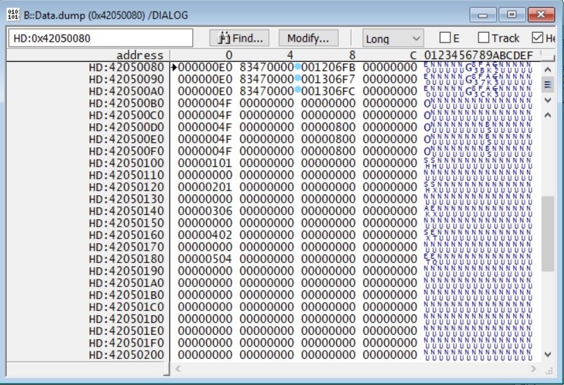
But I could dump the data pointed out at that address 0x4205 0088 (See the attachment TI_Temp.jpg). Right now I see DTEMP value as 0x00 so I’m not sure if that is expected and will change over time?


I would like to know if this is sufficient to monitor or is there any configuration that needs to be done to see the updated Temp values. If so then can TI send us the script file that will help to read out updated Temp value.

  • Hi Vencatesh,

    can you try to reattach the image?

    regards,

    Yordan

  • Hi Venkatesh,

    I don't know the VTM programming. Just wanted to suggest you to look at the control register bits at offset 80h.

    At least, I can see the bit [6] CLRZ is 0, which means temp monitor outputs are currently reset.

    You may also try to set bit [5] SOC to 1 for ADC Start-of Conversion.

    As I can understand, normally the VTM module is controlling the sensors and generates overtemperature alerts automatically, once configured by software. A top-level VTM programming is provided in section 5.2.2.1.5.3.4 VTM Programming Model

    Regards,

    Stan

  • Hi Stan,

    I did follow your recommendation

    i.e., Setting the control register bit [6] CLRZ to 1 and bit [5] SOC to 1. 42050080 is set as 00000061. Refer attachment.

    With the above change I read the temp ADC code value as 1023 which is outside the range or the response I got is 7FF/ 3FF (the EOCZ is toggling) from 42050088.

    I am running the module at ambient. Please let me know what else I need to configure to get the appropriate ADC code or is there a test script you can provide? I have a Lauterbach debugger and can feed the register information as per your suggestion.

  • 1. Please set also bit [7] CLKON_REQ.

    2. Clear bit [0] CBIASSEL  to select bandgap voltage as reference

    Please perform steps one by one. Allow some time to pass and refresh the DTEMP after each step.

    Regards,

    Stan

  • Also, I found the following in a recent spec update:

    "Prior to each single shot sampling, software is expected to reset the sensor's STAT eoc_fc_update field via the sensor's CTRL clrz functionality. Likewise, software is expected to perform the sensor reset prior to transitioning from single shot sampling mode to continuous sampling mode."

  • Hi Stan,

    I see a response from the temperature sensor after setting the bit [7]  CLKON_REQ and clearing bit [0] CBIASSEL. See below. I see the conversion also make sense. I read 50-52C at ambient (22C)

    I am not sure what exactly software needs to do in the ctrl register to reset the EOC_FC_UPDATE. Are you saying software to drive E0( as above) value in the control register every time  to read the temperature value?Please elaborate.

    I also have few questions

    1) Does the internal temperature sensor requires calibration? I don't see it in the User manual

    2)Also how accurate the reading is? Should we need to provide any offset values etc.,.?

    3) Is there a minimum time I need to wait to get the appropriate temperature reading after the processor boots up?

    Thankyou.

  • I'm glad you managed to get a dtemp result.

    Regarding the temp sensor reset:

    Reset Sensors Sequence:
    1. Set the WKUP_VTM_TMPSENS_CTRL_j[6] CLRZ bit to enable the sensor (so that it has the ENA
    input high).
    2. Wait for 900ns to 1us for the sensor clock to toggle and register the updated ENA pin.
    3. Clear WKUP_VTM_TMPSENS_CTRL_j[6] CLRZ to disable and reset the sensor (as it requires an
    ENA transition from 1 to 0 to reset initially) .
    4. Wait for 900ns to 1us for the sensor clock to toggle and register the updated ENA pin.
    5. Now the sensor can be configured and enabled normally.

    Regarding your questions 1-3:

    1. Sensor readings can be fine-tuned  via TRIM registers at offset 4h for each sensor.

    2. This is not specified in the datasheet. Will check internally.

    3. The only time delay specified is between the temp sensor register accesses. It is 1 us as shown in the sequence above. The other delay will come with the waiting for EOCZ to become 0 (end-of-conversion).

    regards,

    Stan

  • Hi Stan,

    Thanks for your response.

     I was able to read the temperature in continuous sampling mode. If I understand correctly then software need to reset the sensor sequence as below

    1. Set the VTM_TMPSENSx_CTRL_j[6] => CLRZ to '0'

    2. Wait for 1us

    3.  Set the VTM_TMPSENSx_CTRL_j[6] => CLRZ to '1'

    4. Wait for 1us

    5. Configure the VTM_TMPSENS_CTRL as 0x000000E0 and read the VTM_ TMPSENSx_STAT.


    Regarding your questions 1-3:

    1. Sensor readings can be fine-tuned  via TRIM registers at offset 4h for each sensor.

    - After reading the VTM_TMPSENS0_TRIM. There are trim settings for few parameters like slope error, offset error, slope of output voltage of bandgap, offset in output voltage of bandgap. I am not sure how to determine these trim values to compensate for the internal temperature sensor!. Are you suggesting to include 0x00000100 in the respective TRIM register? Please clarify

    2. This is not specified in the datasheet. Will check internally.

    - Okay. Please check and let us know.

    3. The only time delay specified is between the temp sensor register accesses. It is 1 us as shown in the sequence above. The other delay will come with the waiting for EOCZ to become 0 (end-of-conversion).

    - Is it something you can estimate the wait time for EOCZ to become 0 or is it a question to the software group?


  • Hi,

    1. I don't think the on-die sensors can be trimmed in the field. This would mean to perform quite enough measurements over the whole scale of temperatures with a very precise thermometer, and very close to the on-die sensors. Not to forget these sensors are on the die, that is, not exposed to user.

    2. I can recall we told J6/OMAP users that the temperature sensors have +/- 2 deg C  of tolerance. I would expect J7 is something similar.

    3. For a hardware continous sampling mode, wait time is set to 0xAA9 periods of the 1,28-MHz sensor clock which makes ~ 2.2 ms. This is FYI only. Software must always poll the EOCz bit and not wait any specific delay.

    Regards,

    Stan

  • Hi Stan,

    The below statement is for an external sensor and not for the on die sensor?

    "Sensor readings can be fine-tuned  via TRIM registers at offset 4h for each sensor".

    Please clarify.

    Thanks and regards,

    Venkatesh

  • 1. Trimming, or calibrating, a sensor means to match the sensor readings with the readings of a known precise sensor.

    2. "Sensor readings can be fine-tuned  via TRIM registers at offset 4h for each sensor".

    (2) --> SoC's hardware provides the ability to tune sensor readings by writing to the VTM_TMPSENS0_TRIM register by software. This can be done ONLY  after (1) has been completed in the factory or by user.