This thread has been locked.

If you have a related question, please click the "Ask a related question" button in the top right corner. The newly created question will be automatically linked to this question.

AM5746: PCIe 5GT/s link retry

Part Number: AM5746

Hi,

Customer board can't link with PCIe 5GT/s. It happens in their application that connecting AM5746(EP)---AM5746(RC).

Customer checked PCIECTRL_TI_CONF_DEVICE_CMD (0x51002104) register because find the cause.
RC's register change was confirmed.

PCIECTRL_TI_CONF_DEVICE_CMD
NG
0x0000 0000
0x0000 0009
0x0000 000D
0x0000 0000

OK
0x0000 0000
0x0000 0009
0x0000 000D
0x0000 0045

EP's
NG: 0x0000 0000 -> 0000 0000
OK: 0x0000 0000 -> 0000 0045

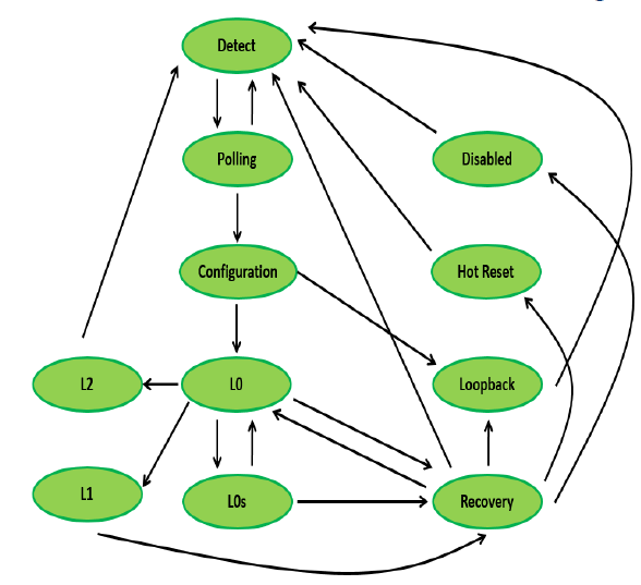
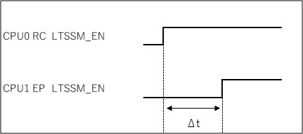
They checked PDK driver, but they didn't find any processing that set LTSSM_EN Field to 1.
We assume that HW set this field to 0.


Question 1:
Is LTSSM_EN set to 0 due to external factors?

Question 2:
Would you tell me how to retry if link fail (=LTSSM_EN:0)?

Customer's board
bios_6_76_00_08
pdk_am57xx_1_0_11

Regards,
Rei

  • Hi,

    I look at the register description.
     PCIECTRL_TI_CONF_DEVICE_CMD:LTSSM_EN
    LTSSM enable: start the PCI link (This bit is CLEARED BY FUNDAMENTAL RESET)

    Question 1:
    Is FUNDAMENTAL RESET a Fundamental hardware reset?
    (TRM:25.9.4.4.2.2 PCIe Standard Specific Resets to the PCIe Core Logic)

    Question 2:
    If Q1 is yes, please tell us about the following.
    ・What is Vmain?
    ・Would you tell me how to check the threshold

    Sorry for asking so many times..

    Regards, Rei

  • Link training is initiated via software by setting LTSSM_EN=1.  The LTSSM_EN bit will reset back to 0 if the link training fails.  The most common cause of link training failure is not using a Common Refclk between the RC and EP.  Can you let us know your Refclk configuration in terms of HW connections and SW settings?

  • Hi B.C.,

    Thank you for your reply. Does it mean that Fundamental reset has not happened?

    They use same refclk. What should we check for SW settings? (Which register should I check? TRM P.730 PCIe PHY DPLL Recommended Values?)

    Regards, Rei

  • That's good that a Common Refclk is used.  Please check that the REFSEL bit (bit 7) of register CM_CLKMODE_APLL_PCIE is set to 0x1 to make sure that the device is using the external 100MHz Refclk from the ACSPCIE buffer.  Also please check that the ACSPCIe buffer is in RX mode by setting 0x2 in the PCIE_TX_RX_CONTROL field (bits 17:16) of register CTRL_CORE_SMA_SW_6.

    The Error IRQs can be used to help determine the underlying error conditions in case of a link failure.

  • Hi,

    Thank you for your reply. I gave your advice to the customers, and they are checking it.
    Customers can't 5GT/s link when Reset/PowerOn. (8 times in 10 times)
    Now they do link training again. (set LTSSM:1) They have almost improved. Thank you for your advice.

    However, they are looking for the root cause. So they have another questions.

    "This bit is CLEARED BY FUNDAMENTAL RESET"
    TRM description is written. Also you said
    ”The LTSSM_EN bit will reset back to 0 if the link training fails. "

    Question 1:
    Is FUNDAMENTAL RESET "Fundamental hardware reset"?
    (TRM:25.9.4.4.2.2 PCIe Standard Specific Resets to the PCIe Core Logic)

    If Q1 is yes, please tell us about the following.
    Question 2:
    ・What is Vmain?
    (TRM: ..upon PCIe controller's main power supply (Vmain))
    ・Would you tell me how to check the threshold
    (TRM: ..defined threshold by the PCIe RC)

    Question 3:
    What is Link training fails? LTSSM is not stable to L0? can't transfer L0?

    Question 4:

    When LTSSM_EN 1→0, changed from ”Configuration” to ”Disable”?

    Question 5
    Are There any other cause (LTSSM_EN=0)
    ・ FUNDAMENTAL RESET
    ・ Link training fail

    Sorry for many questions...

    Regards, Rei

  • The PCIe Link-down reset condition is called an internal fundamental reset.  The LINK_REQ_RST IRQ can be checked to confirm this reset is occurring.  The "Vmain" discussed in the reset section is referring to the power supply for the SoC.  It is unlikely that "Vmain" is the source of the link-up issue, but the system should of course be designed to detect issues such as dips in the SoC power supplies.

    Correct, link training success means reaching the L0 state.  When LTSSM_EN 1->0, the PCIe controller stops execution of the PCIe state machine entirely.

    The most likely causes of the link training failure are Refclk integrity and signal integrity.

  • Thank you for your support. Customers have confirmed the register. These were right.

    CM_CLKMODE_APLL_PCIE: REFSEL(bit7)=0x1
    PCIE_CORE_SMA_SW_6: PCIE_TX_RX_CONTROL(bits 17:16)=0x2

    Sorry for many times,,, Customers want answers to each question.

    Question 1:
    "Hardware fundamental reset"(TRM 24.9.4.4.2.2) = internal fundamental reset?

    Question 2:
    Vmain = vdd?
    (DS 5.4 Core voltage domain supply)

    Question 3:
    Would you tell me how to check "threshold"?(TRM 24.9.4.4.2.2)
    (TRM: ..defined threshold by the PCIe RC)

    Question 4:
    When LTSSM_EN is cleared by internal fundamental reset, how does LTSSM transition?

    Thank you as always.
    Regards, Rei

  • Q1: Yes, they have the same effect, but different triggers.  i.e. the internal fundamental reset is trigged by a link down condition.

    Q2: Vmain should be considered to be the aggragate of all SoC power supplies

    Q3: The MIN/MAX threshold limits for each SoC power supply are listed in the datasheet

    Q4: When LTSSM_EN is cleared, the LTSSM is exited

    A few of recommendations for further debug:

    1) Enable and log all PCIe errors/IRQs

    2) Log the LTSSM state (high-frequency/low-latency logging recommended) through the link training process

    2) Try synchronizing the setting of LTSSM_EM=1 between the RC and EP

  • Hi B.C.

    Thank you for answering many questions. Customer is logging the LTSSM state.
    This table shows the log when the logging device is RC and destination is EP.
    When DEVICE_CMD is changed, they checkd the register.
    -PCIECTRL_TI_CONF_DEVICE_CMD (0x5100 2104 / 0x5180 2104)

    Question 1:
    We checked LTSSM_EN state, but we can't understand the cause.
    Do you have any thoughts about what the cause might be?

    Question 2:
    Customer has tried a lot, as you answered, the timing of LTSSM_EN=1 seems to be important.
    >>>Try synchronizing the setting of LTSSM_EM=1 between the RC and EP
    Could you tell us the allowable time(ΔT) for synchronizating?

    Regards, Rei

  • Thanks for the LTSSM log.  It looks like the system is having trouble when it tries to change speed from Gen 1 to Gen 2.  Please modify the system to limit the speed to Gen 1 and confirm that works OK.

    Regarding synchronization, please try targeting <12ms based on the Detect state timeouts.

    Also, please confirm against the latest TRM that the steps and settings listed in the following tables are being followed in the system:

    - PCIePHY Subsystem Low-Level Programming Sequence

    - Preferred PCIe_PHY_RX SCP Register Settings

  • Hi B.C.

    Thank you for your reply. Customers are checking on Sequence and Register for Gen1 and TRM.

    If we want to synchronize RC and EP within 12ms, they need to adjust the timing with another signal (ex.GPIO).
    The customer's board is difficult to synchronize, so each of the RC/EPs repeats the set of LTSSM_EN bits. (until the link is successful).
    Is this method OK?

    Regards, Rei

  • Instead of repeating the setting of LTSSM_EN bits, I would instead recommend to add software delays before setting LTSSM_EN.  Adjust the delay so that PCIe TX signals on both sides of the link start toggling at the same time.  This would require probing the PCIe AC coupling caps on the board to observe alignment.

  • Hi B.C.

    Thank you for your reply.

    We could understand that add software delays before setting LTSSM_EN.

    However, we can't understand that timing, delays(?? ms?) and probing.

    Could you please tell us more about this?
    ・What should we probe?
    ・how to decide the delay times.
    ・Where to add delay (ex:add delays after setting XX register)

    Regards, Rei

  • ・What should we probe?

    Probing on the AC coupling capacitors on the pcie_txp0 signals of both devices is sufficient.


    ・how to decide the delay times.

    If the pcie_txp0 signal on device A starts toggling before device B, add delay to device A


    ・Where to add delay (ex:add delays after setting XX register)

    Add delay before setting LTSSM_EN = 1

  • Hi B.C.,

    Thank you for your reply.

    They decided to repeat the set of LTSSM_EN due to difficult synchronization. Thank you for your support!!