This thread has been locked.

If you have a related question, please click the "Ask a related question" button in the top right corner. The newly created question will be automatically linked to this question.

TMS320C6457: Inquiry about POR

Part Number: TMS320C6457

Hello team,

Our customer is developing system board with TMS320C6457, customer encountered the problem which was related to POR.

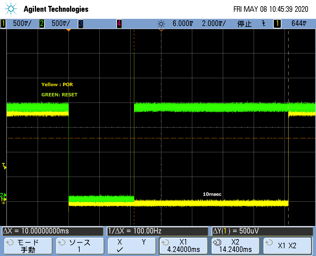
This board is working fine after system power-up, however, when POR was executed after system power-up, system seems freeze as follows (Power is keeping to supply). Although I requested customer to capture RESETSTAT in addition, RESETSTAT terminal was implemented as N.C, unfortunately. Customer is using EMIFABoot mode.

As far s I checked datasheet[7.6.1 Power-on Reset], it seems, device power-up cycle is not required to initiate a power-on reset.Is there any limitation for POR execution? If customer wants to do system-reset, should they initiate “Warm Reset”?

It will be appreciated if you will be share Expert’s advice/comments on this.

Best regards,

Miyazaki

  • Hi team,

    Can we have any comments on this, please?

    I'm sorry for rushing  you but we'd like to know the current status.

    Best regards,

    Miyazaki

  • Hi Miyazaki,

    The POR and RESET signals shown look like they are valid based on the timing shown in the data manual.  Applying a POR after the power supplies are present is also valid.  Does the clock continue through the reset pulses?  Can the customer probe the EMIFA address and control signals to see if the device attempts to reboot?

    Regards, Bill

  • Hi Bill,

    Thanks for your comments on this. I’m requesting customer to probe AECLKOUT pin of EMIFA. Is that O.K? And then, although I requested to probe the EMIFA address and control signals, it seems customer is not able to do it on their board.

    When I will receive customer’s investigation for clock, I’ll let you know as soon as possible.


    Best regards,

    Miyazaki

  • Hi Mayazaki,

    The AECLKOUT is not the best signal to probe.  It's only present if they are using synchronous memory and it is just a clock output.  Better signals would be the CE and one of the lower addresses of the boot memory.  If the CE is active and the addresses are toggling than the device is attempting to boot from that device. 

    Has the customer attempted to put a JTAG probe on the device after the reset is applied?  Can he read the DEVSTAT registers after power up and after the reset is applied to see whether the bootmode is latched correctly?  How are the GPIO pins shared with bootmode used on the customer board?  Another possibility is that the customer is using these as inputs that are driven by some circuit once the board is operational.  If the circuit driving these pins is not disabled when the POR is applied, the wrong bootmode may be latched.

    Regards, Bill

  • Hi Bill,

    Thanks for your supporting as usual. I shared your comments on this with customer. Also, I’m requesting customer to check the DEVSTAT registers and GPIO[4:1] during attempting POR. when I will receive this result, I'll let you know.

    Anyway, I received the result of AECLKOUT investigation. AECLKOUT behavior is as follows. this result may not be helpful for this analysis... , but, please let me to share it.

    Outputting 80MHz à [Issue POR]à5MHzà Outputting 80MHzà5MHzà Outputting 80MHz


    Best regards, Miyazaki

  • Hello Bill,

    Customer was able to gain BOOTMODE value in DEVSTAT registers after POR-issue occurred. It seems, BOOTMODE[3:0] shows " 0101 = EMIFA Boot ". Just to be sure, customer is trying to check GPIO[4:1] during attempting POR.

    If customer needs to investigate any other portions, please share your advice/comments on this.

    I really appreciate your help.

    Best regards,

    Miyazaki

  • Hi Miyazaki,

    Since the BOOTMODE is EMIFA the device should start reading the contents of the memory device.  You should see the ACE3 go active and the address lines start to increment.  If you observe the ACE3 chip enable and the addresses you should be able to check the internal memory to see if the correct information ls loaded using JTAG.  You can also use the JTAG to halt the operation after the POR to see where the program counter is.  This may give a clue to what is occuring.

    Regards, Bill

  • Hello Bill,

    Thanks for your comments. I will request customer to check ACE3 pin if you will be able to check this pin on their board.

    Regarding program counter after POR, I’m not sure if customer will be able to check this. because POR resets entire chip including emulation logic. Customer told us that CCS shows “In Reset(Secure)” after POR, previously. Anyway, I’d like to request customer to check them.

    Best regards,

    Miyazaki

  • Hi Miyazaki,

    The customer should be able to have the JTAG connected and have the processor in run free mode.  Once the PORz has toggled and the part is out of reset, they should be able to reconnect with the JTAG and see what state the device is in.

    Regards, Bill