This thread has been locked.

If you have a related question, please click the "Ask a related question" button in the top right corner. The newly created question will be automatically linked to this question.

AM3354: Getting Bands In Images When Reducing 24bpp to 18bpp

Part Number: AM3354

We are using a 3.5" LCD with a 18bpp interface. The processor outputs 24bpp from the processor and connect only the 6 MSB of each color to the LCD connector.

We have a custom driver for the LCD with the display mode set up specifically for this display:

static const struct drm_display_mode default_mode = {
	.clock          = 10563,            // Pixel Clock = 10.563MHz
	.hdisplay       = 320,
	.hsync_start    = 320 + 38,         // Horizontal Back Porch = 38
	.hsync_end      = 320 + 38 + 2,     // Horizontal Front Porch = 2
	.htotal         = 320 + 38 + 2 + 4, // Horizontal Sync = 4
	.vdisplay       = 480,
	.vsync_start    = 480 + 8,          // Vertical Back Porch = 8
	.vsync_end      = 480 + 8 + 4,      // Vertical Front Portch = 4
	.vtotal         = 480 + 8 + 4 + 4,  // Vertical Sync = 4
	.vrefresh       = 60,
	.flags          = DRM_MODE_FLAG_NVSYNC | DRM_MODE_FLAG_NHSYNC,
};

Here is the output of my gfx_check.sh:

./gfx_check.sh 
WSEGL settings
[default]
WindowSystem=libpvrDRMWSEGL.so
DefaultPixelFormat=ARGB8888
------
ARM CPU information
processor	: 0
model name	: ARMv7 Processor rev 2 (v7l)
BogoMIPS	: 597.60
Features	: half thumb fastmult vfp edsp neon vfpv3 tls vfpd32 
CPU implementer	: 0x41
CPU architecture: 7
CPU variant	: 0x3
CPU part	: 0xc08
CPU revision	: 2

Hardware	: Generic AM33XX (Flattened Device Tree)
Revision	: 0000
Serial		: 34:03:de:73:a9:65
------
SGX driver information
Version SGX_DDK_Linux_XOrg sgxddk 1.17@4948957 (release) omap_linux
System Version String: SGX revision = 125
------
Framebuffer settings

mode "320x480-0"
	# D: 0.000 MHz, H: 0.000 kHz, V: 0.000 Hz
	geometry 320 480 320 480 32
	timings 0 0 0 0 0 0 0
	accel true
	rgba 8/16,8/8,8/0,0/0
endmode

------
Rotation settings
0
------
Kernel Module information
Module                  Size  Used by
g_mass_storage         16384  0
usb_f_mass_storage     45056  2 g_mass_storage
libcomposite           53248  2 g_mass_storage,usb_f_mass_storage
musb_dsps              20480  0
musb_hdrc              73728  1 musb_dsps
pm33xx                 16384  0
wkup_m3_ipc            16384  1 pm33xx
wkup_m3_rproc          16384  1
pvrsrvkm              397312  0
remoteproc             45056  2 wkup_m3_rproc,wkup_m3_ipc
omap_aes_driver        24576  0
ti_emif_sram           16384  1 pm33xx
crypto_engine          16384  1 omap_aes_driver
omap_sham              28672  0
omap_crypto            16384  1 omap_aes_driver
goodix                 20480  0
rtc_omap               20480  1
musb_am335x            16384  0
omap_wdt               16384  0
sch_fq_codel           20480  1
------
Boot settings
console=ttyO0,115200n8 root=PARTUUID=9066e1f1-02 rw rootfstype=ext4 rootwait
------
Linux Kernel version
Linux ercss5 4.19.38-g4dae378bbe #1 PREEMPT Wed Sep 30 16:46:51 UTC 2020 armv7l GNU/Linux

The output of my qt_env.sh file:

#!/bin/sh

### QT Environment Variables ###
export QT_QPA_EVDEV_TOUCHSCREEN_PARAMETERS="rotate=180"
export SSL_CERT_FILE=/etc/ssl/certs/ca-certificates.crt
export QT_QPA_EGLFS_KMS_CONFIG=/etc/qt5/eglfs_kms_cfg.json
export QT_QPA_EGLFS_INTEGRATION=none
export QT_QPA_PLATFORM=eglfs
export QT_QPA_EGLFS_PHYSICAL_HEIGHT=49
export QT_QPA_EGLFS_PHYSICAL_WIDTH=73
export QT_QPA_EGLFS_DEBUG=1
export QSG_INFO=1

And the Qt debug output when running the application:

qt.scenegraph.general: threaded render loop
qt.scenegraph.general: Using sg animation driver
qt.scenegraph.general: Animation Driver: using vsync: 16.67 ms
Created context for format QSurfaceFormat(version 2.0, options QFlags<QSurfaceFormat::FormatOption>(), depthBufferSize 24, redBufferSize -1, greenBufferSize -1, blueBufferSize -1, alphaBufferSize -1, stencilBufferSize 8, samples -1, swapBehavior QSurfaceFormat::SwapBehavior(DoubleBuffer), swapInterval 1, colorSpace QSurfaceFormat::ColorSpace(DefaultColorSpace), profile  QSurfaceFormat::OpenGLContextProfile(NoProfile)) with config:
	EGL_BUFFER_SIZE: 32
	EGL_ALPHA_SIZE: 8
	EGL_BLUE_SIZE: 8
	EGL_GREEN_SIZE: 8
	EGL_RED_SIZE: 8
	EGL_DEPTH_SIZE: 24
	EGL_STENCIL_SIZE: 8
	EGL_CONFIG_CAVEAT: 12344
	EGL_CONFIG_ID: 8
	EGL_LEVEL: 0
	EGL_MAX_PBUFFER_HEIGHT: 2048
	EGL_MAX_PBUFFER_PIXELS: 4194304
	EGL_MAX_PBUFFER_WIDTH: 2048
	EGL_NATIVE_RENDERABLE: 0
	EGL_NATIVE_VISUAL_ID: 0
	EGL_NATIVE_VISUAL_TYPE: 0
	EGL_SAMPLES: 0
	EGL_SAMPLE_BUFFERS: 0
	EGL_SURFACE_TYPE: 1541
	EGL_TRANSPARENT_TYPE: 12344
	EGL_TRANSPARENT_BLUE_VALUE: 0
	EGL_TRANSPARENT_GREEN_VALUE: 0
	EGL_TRANSPARENT_RED_VALUE: 0
	EGL_BIND_TO_TEXTURE_RGB: 0
	EGL_BIND_TO_TEXTURE_RGBA: 0
	EGL_MIN_SWAP_INTERVAL: 1
	EGL_MAX_SWAP_INTERVAL: 10
qt.scenegraph.general: Using sg animation driver
qt.scenegraph.general: Animation Driver: using vsync: 16.67 ms
qt.scenegraph.general: texture atlas dimensions: 512x512
qt.scenegraph.general: R/G/B/A Buffers:   8 8 8 8
qt.scenegraph.general: Depth Buffer:      24
qt.scenegraph.general: Stencil Buffer:    8
qt.scenegraph.general: Samples:           0
qt.scenegraph.general: GL_VENDOR:         Imagination Technologies
qt.scenegraph.general: GL_RENDERER:       PowerVR SGX 530
qt.scenegraph.general: GL_VERSION:        OpenGL ES 2.0 build 1.17@4948957
qt.scenegraph.general: GL_EXTENSIONS:     GL_OES_depth24 GL_OES_surfaceless_context GL_OES_texture_float GL_IMG_uniform_buffer_object GL_OES_element_index_uint GL_OES_rgb8_rgba8 GL_IMG_read_format GL_OES_fbo_render_mipmap GL_OES_depth_texture GL_KHR_debug GL_OES_texture_half_float GL_EXT_shader_texture_lod GL_OES_EGL_image_external GL_OES_standard_derivatives GL_IMG_texture_compression_pvrtc GL_IMG_texture_format_BGRA8888 GL_IMG_texture_npot GL_OES_packed_depth_stencil GL_EXT_texture_rg GL_IMG_multisampled_render_to_texture GL_IMG_program_binary GL_OES_vertex_half_float GL_EXT_texture_storage GL_OES_egl_sync GL_OES_fragment_precision_high GL_EXT_multisampled_render_to_texture GL_OES_mapbuffer GL_OES_EGL_image GL_OES_vertex_array_object GL_EXT_texture_format_BGRA8888 GL_EXT_multi_draw_arrays GL_IMG_shader_binary GL_OES_compressed_ETC1_RGB8_texture GL_EXT_blend_minmax GL_OES_get_program_binary GL_OES_required_internalformat GL_EXT_discard_framebuffer
qt.scenegraph.general: Max Texture Size: 2048
qt.scenegraph.general: Debug context:    false

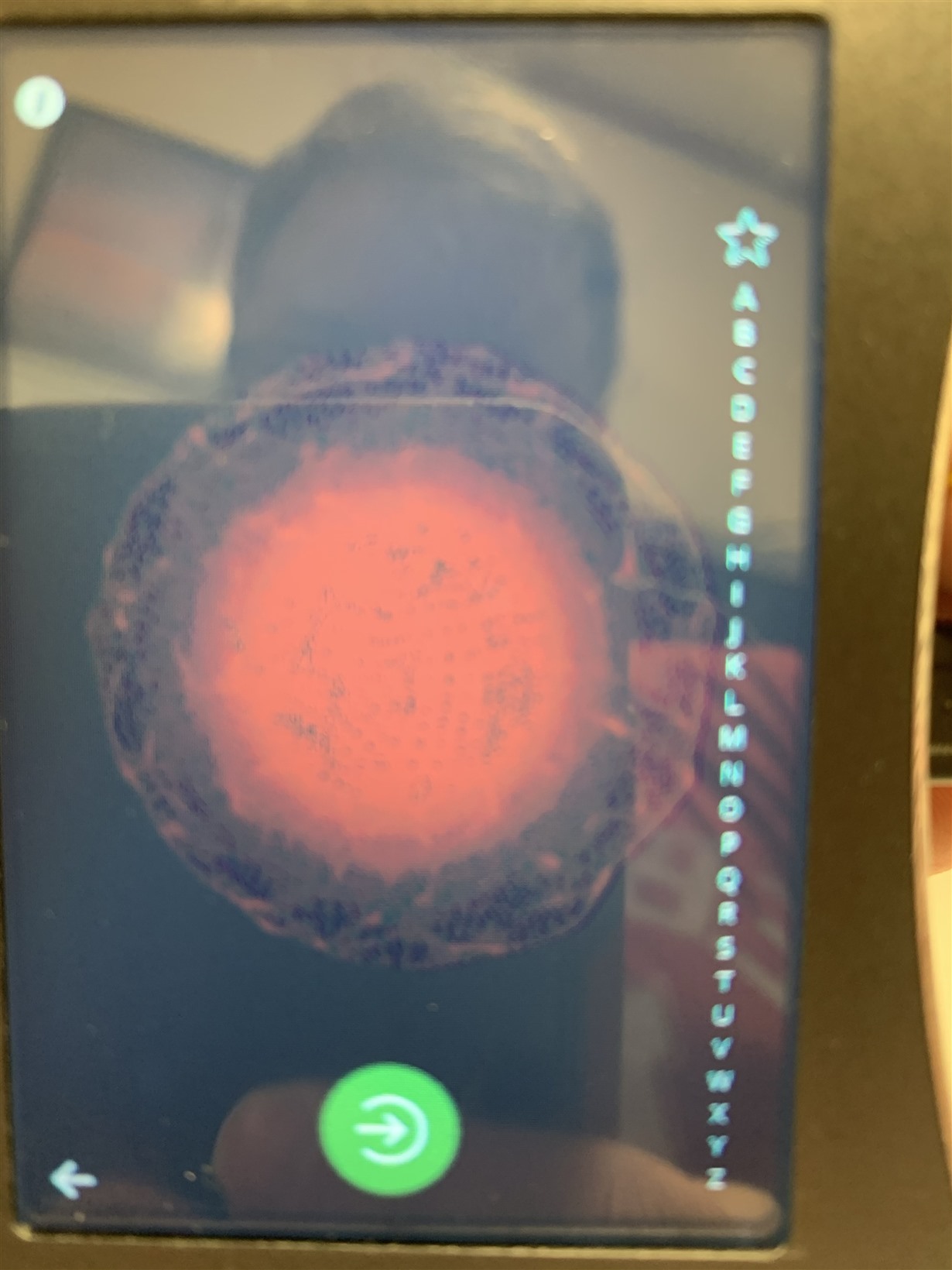
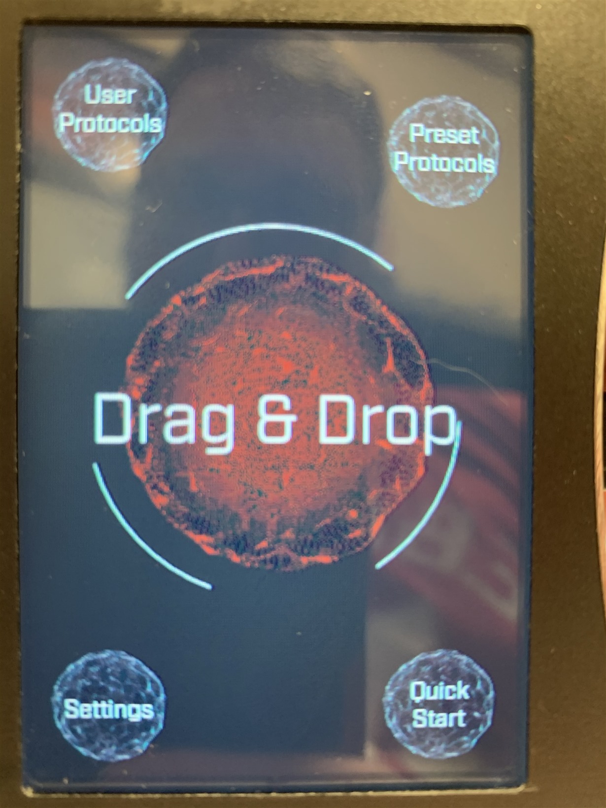
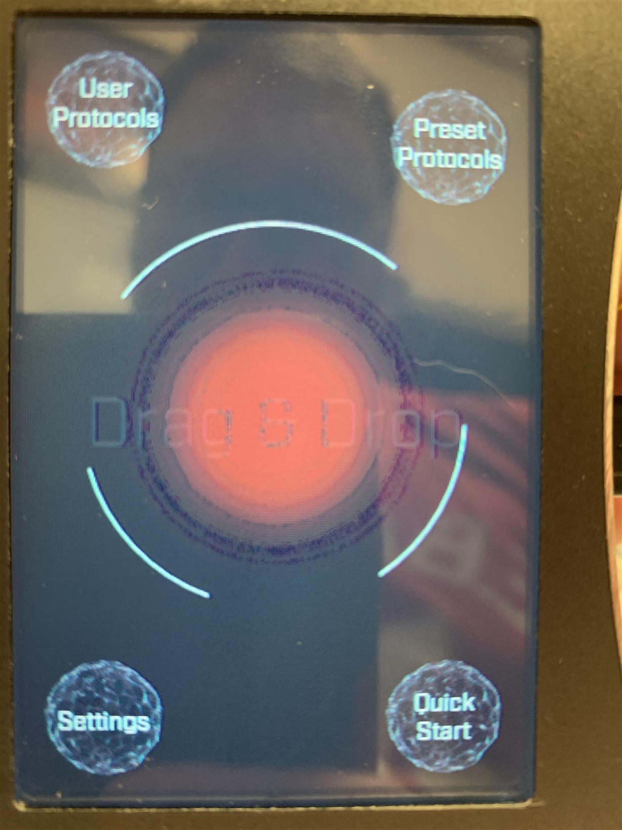
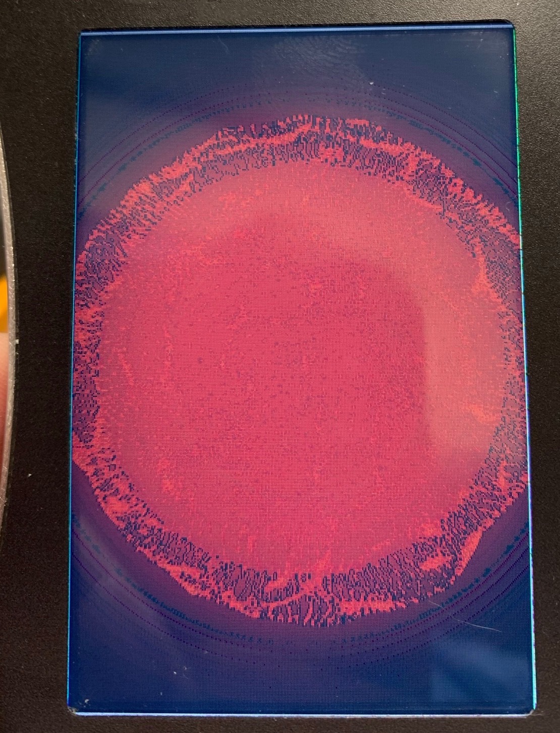
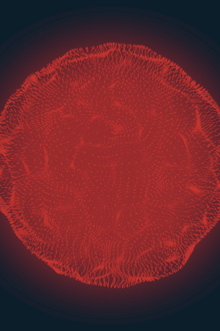
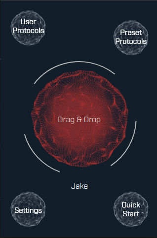
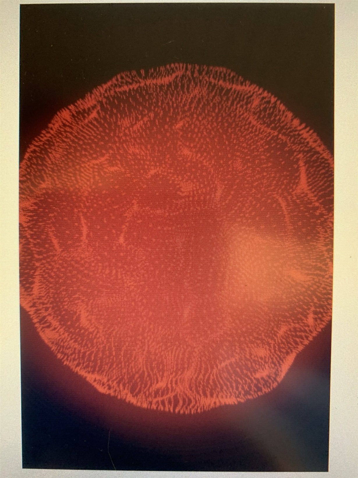
Finally, here are some images describing the color issues. The center circle is supposed to be a subtle fade from red to the background color and looks proper when run on a PC. The black artifacts in the "orb" aren't supposed to be there either.:

Thank you for any help,

Jake

  • Hi Jake,

    As an experiment, let's isolate GPU from testing and verify the LCD, by running the commands: "kmsprint -l (it shows the supported formats) and kmstest -f <pixfmt>". If your LCD supports AR24 (ARGB8888) then use AR24 as the pixfmt. Also, do you see the same results when running the Qt application with linuxfb flag?

    With regards to the above pictures, could you please explain which picture was captured on PC and which picture was captured on AM3354?

    Regards,
    Krunal

  • Krunal,

    Thank you for your response.

    I get the same result when running Qt with the linuxfb flag. I will also include images of what the screen should look like below.

    Here is the result from the commands:

    kmsprint -l
    Connector 0 (31) DPI-1 (connected)
    Encoder 0 (30) NONE
    Crtc 0 (29) 320x480 10.563 320/38/2/4 480/8/4/4 60 (58.51)
    Plane 0 (28) fb-id: 37 (crtcs: 0) 0,0 320x480 -> 0,0 320x480 (BG16 RG24 XR24)
    FB 37 320x480

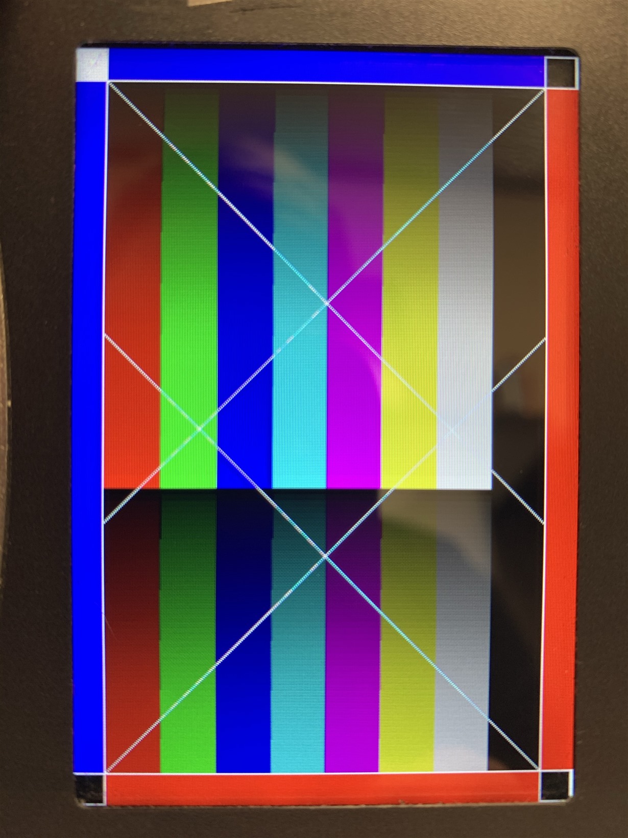
    And the image when I run this:

    kmstest -f RG24
    Connector 0/@31: DPI-1
      Crtc 0/@29 (plane 0/@28): 320x480 10.563 320/38/2/4 480/8/4/4 60 (58.51) 0xa 0x48
        Fb 35 320x480-RG24

    I displayed just a PNG image similar to what I'm trying to display using the Linux frame buffer platform. Here is the result:

    And here is the raw image:

    And finally here is what the screen should look like based on the application running on PC (The DPI hasn't properly been applied yet, so there is a difference in the text size):

    Thank you for your help,

    Jake

  • Hi Jake,

    Thank you for the details. I just wanted to confirm that the arrows in the below image captures the bands that you are mentioning above:

    Also, please correct me if I am wrong but the same bands do not appear when you use a 24bpp LCD. 

    Regards,
    Krunal

  • Krunal,

    Yes, those bands. Also, the dark pixels around the outside of the "orb" are not accurate either.

    I viewed this image on another device with a 24bpp connection using the same application used to view this image on the other device and it looks good.

    Thanks again,

    Jake

  • I wanted to clarify with the image in my last post. This was done on a different platform with an older kernel and version of Qt. The LCD is also being run through an LVDS converter so it may not be an apples-to-apples comparison. We don't have a 24-bit connector to connect a 24-bit display to this same platform unfortunately.

  • HI Jake,

    Could you please run the kmstest -f XR24 and share the LCD screenshot?

    Regards,
    Krunal

  • Hey Krunal,

    Here is a picture of the LCD while displaying kmstest -f XR24

    Thank you,

    Jake

  • Hi Jake,

    Is it possible for you to share a simple application that I could run on my side? 

    Regards,
    Krunal

  • Krunal,

    I've included a simple Qt application that will display a provided PNG. Just run qt-image-viewer /path/to/file.png. The provided binary is built for ARM with Qt 5.11. I also included the source and some PNG files.

    Regards,

    Jake

    qt-image-viewer.zip

  • Krunal,

    Was that application any use to you? Are there any more suggestions?

    Thank you,

    Jake

  • Hi Jake,

    I have ran your application on my setup and I am not able to replicate the issue on my AM335x GP EVM. We are working on a script that will capture the pixel data from the framebuffer to a file. As of now, it is hard to tell if the LCDC is given the bad data or if LCDC is causing the corruption. I will get back to you by early next week.

    Regards,
    Krunal

  • Hi Jake,

    Let's try to capture the framebuffer using the following commands:
    1. Launch your Qt application
    2. Upon successful launch, suspend the application using the "Ctrl + z" 
    3. Execute the following command: "cat /sys/kernel/debug/dri/0/framebuffer"
    4. It will list all the framebuffers and for each buffer, capture the paddr and size
    5. Capture the raw data using the command: rwmem -R paddr+size > fb.data
    6. Copy the data into your Linux machine and run the command: convert -depth 8 -size 800x480 -color-matrix "0 0 1 0 1 0 1 0 0" -alpha deactivate rgba:fb.data fb.png (Change the width and height based on your setup)

    Please try the above steps for each framebuffer and share the output images. 

    Regards,
    Krunal

  • Krunal,

    Thank you for your response! I've followed your steps and the resulting PNGs look as they should without any banding.

    Here is a compressed file with the framebuffer output and all of the data and PNGs:

    fb_data.zip

    Thank you,

    Jake

  • Hi Jake,

    The framebuffer provided to display is correct and I am wondering if you have modified the LCDC driver. It seems like you are using a customer driver and I am assuming you are not using the default TI driver?

    Regards,
    Krunal

  • Krunal,

    We are using a custom panel driver, which I've attached below:

    panel-sitronix-st7796s.c
    /*
     * Copyright (C) 2017 Free Electrons
     * Modified 2020, CSS. For specific st7796s controller.
     *
     * This program is free software; you can redistribute it and/or
     * modify it under the terms of the GNU General Public License version
     * 2 as published by the Free Software Foundation.
     */
    
    #include <linux/gpio/consumer.h>
    #include <linux/regulator/consumer.h>
    #include <linux/spi/spi.h>
    
    #include <drm/drmP.h>
    #include <drm/drm_panel.h>
    
    #define ST7796S_NOP_CMD		0x00 // No operation
    #define ST7796S_SWRESET_CMD	0x01 // Software Reset
    #define ST7796S_RDDID_CMD	0x04 // Read Display ID
    #define ST7796S_RDNUMED_CMD	0x05 // Read Number of errors on DSI
    #define ST7796S_RDDST_CMD	0x09 // Read Display Status
    #define ST7796S_RDDPM_CMD	0x0A // Read display power
    #define ST7796S_RDDMADCTL_CMD	0x0B // Read display MADCTL
    #define ST7796S_RDDCOLMOD_CMD	0x0C // Read Display Pixel Format
    #define ST7796S_RDDIM_CMD	0x0D // Read Display Image Mode
    #define ST7796S_RDDSM_CMD	0x0E // Read Display Signal Mode
    #define ST7796S_RDDSDR_CMD	0x0F // Read Display Self-Diagnostic Result
    #define ST7796S_SLPIN_CMD	0x10 // Sleep In
    #define ST7796S_SLPOUT_CMD	0x11 // Sleep Out
    #define ST7796S_PTLON_CMD	0x12 // Partial Display Mode On
    #define ST7796S_NORON_CMD	0x13 // Normal Display Mode On
    #define ST7796S_INVOFF_CMD	0x20 // Display Inversion Off
    #define ST7796S_INVON_CMD	0x21 // Display Inversion On
    #define ST7796S_DISPOFF_CMD	0x28 // Display Off
    #define ST7796S_DISPON_CMD	0x29 // Display On
    #define ST7796S_CASET_CMD	0x2A // Column Address Set
    #define ST7796S_RASET_CMD	0x2B // Row Address Set
    #define ST7796S_RAMWR_CMD	0x2C // Memory Write
    #define ST7796S_RAMRD_CMD	0x2E // Memory Read
    #define ST7796S_PTLAR_CMD	0x30 // Partial Area
    #define ST7796S_VSCRDEF_CMD	0x33 // Vertical Scrolling Definition
    #define ST7796S_TEOFF_CMD	0x34 // Tearing Effect Line Off
    #define ST7796S_TEON_CMD	0x35 // Tearing Effect Line On
    #define ST7796S_MADCTL_CMD	0x36 // Memory Data Access Control
    #define ST7796S_VSCSAD_CMD	0x37 // Vertical Scroll Start Address of RAM
    #define ST7796S_IDMOFF_CMD	0x38 // Idle Mode Off
    #define ST7796S_IDMON_CMD	0x39 // Idle Mode On
    #define ST7796S_COLMOD_CMD	0x3A // Interface Pixel Format
    #define ST7796S_WRMEMC_CMD	0x3C // Write Memory Continue
    #define ST7796S_RDMEMC_CMD	0x3E // Read Memory Continue
    #define ST7796S_STE_CMD		0x44 // Set Tear Scanline
    #define ST7796S_GSCAN_CMD	0x45 // Get Scanline
    #define ST7796S_WRDISBV_CMD	0x51 // Write Display Brightness
    #define ST7796S_RDDISBV_CMD	0x52 // Read Display Brightness Value
    #define ST7796S_WRCTRLD_CMD	0x53 // Write CTRL Display
    #define ST7796S_RDCTRLD_CMD	0x54 // Read CTRL Display
    #define ST7796S_WRCABC_CMD	0x55 // Write Adaptive Brightness Control
    #define ST7796S_RDCABC_CMD	0x56 // Read Adaptive Brightness Control
    #define ST7796S_WRCABCMB_CMD	0x5E // Write CABC Minimum Brightness
    #define ST7796S_RDCABCMB_CMD	0x5F // Read CABC Minimum Brightness
    #define ST7796S_RDFCS_CMD	0xAA // Read First Checksum
    #define ST7796S_RDCFCS_CMD	0xAF // Read Continue Checksum
    #define ST7796S_RDID1_CMD	0xDA // Read ID1
    #define ST7796S_RDID2_CMD	0xDB // Read ID2
    #define ST7796S_RDID3_CMD	0xDC // Read ID3
    #define ST7796S_IFMODE_CMD	0xB0 // Interface Mode Control
    #define ST7796S_FRMCTR1_CMD	0xB1 // Frame Rate Control 1
    #define ST7796S_FRMCTR2_CMD	0xB2 // Frame Rate Control 2
    #define ST7796S_FRMCTR3_CMD	0xB3 // Frame Rate Control 3
    #define ST7796S_DIC_CMD		0xB4 // Display Inversion Control
    #define ST7796S_BPC_CMD		0xB5 // Blanking Porch Control
    #define ST7796S_DFC_CMD		0xB6 // Display Function Control
    #define ST7796S_EM_CMD		0xB7 // Entry Mode Set
    #define ST7796S_PWR1_CMD	0xC0 // Power Control 1
    #define ST7796S_PWR2_CMD	0xC1 // Power Control 2
    #define ST7796S_PWR3_CMD	0xC2 // Power Control 3
    #define ST7796S_VCOM_CMD	0xC6 // VCOM Offset Register
    #define ST7796S_NVMADW_CMD	0xD0 // NVM Address/Data Write
    #define ST7796S_NVMBPROG_CMD	0xD1 // NVM Byte Program
    #define ST7796S_NVMSTRD_CMD	0xD2 // NVM Status Read
    #define ST7796S_RDID4_CMD	0xD3 // Read ID4
    #define ST7796S_PGC_CMD		0xE0 // Positive Gamma Control
    #define ST7796S_NGC_CMD		0xE1 // Negative Gamma Control
    #define ST7796S_DGC1_CMD	0xE2 // Digital Gamma Control 1
    #define ST7796S_DGC2_CMD	0xE3 // Digital Gamma Control 2
    #define ST7796S_DOCA_CMD	0xE8 // Display Output Control Adjust
    #define ST7796S_CSCON_CMD	0xF0 // Command Set Control
    #define ST7796S_SPIRC_CMD	0xF8 // SPI Read Control
    
    #define ST7796S_TEST(val, func)		\
    	do {				\
    		if ((val = (func)))	\
    			return val;	\
    	} while (0)
    
    struct st7796s {
    	struct drm_panel panel;
    	struct spi_device *spi;
    	struct gpio_desc *reset;
    	struct backlight_device *backlight;
    	struct regulator *power;
    };
    
    enum st7796s_prefix {
    	ST7796S_COMMAND = 0,
    	ST7796S_DATA = 1,
    };
    
    static inline struct st7796s *panel_to_st7796s(struct drm_panel *panel)
    {
    	return container_of(panel, struct st7796s, panel);
    }
    
    static int st7796s_spi_write(struct st7796s *ctx, enum st7796s_prefix prefix,
    				 u8 data)
    {
    	struct spi_transfer xfer = { };
    	struct spi_message msg;
    	u16 txbuf = ((prefix & 1) << 8) | data;
    
    	spi_message_init(&msg);
    
    	xfer.tx_buf = &txbuf;
    	xfer.bits_per_word = 9;
    	xfer.len = sizeof(txbuf);
    
    	spi_message_add_tail(&xfer, &msg);
    	return spi_sync(ctx->spi, &msg);
    }
    
    static int st7796s_write_command(struct st7796s *ctx, u8 cmd)
    {
    	return st7796s_spi_write(ctx, ST7796S_COMMAND, cmd);
    }
    
    static int st7796s_write_data(struct st7796s *ctx, u8 cmd)
    {
    	return st7796s_spi_write(ctx, ST7796S_DATA, cmd);
    }
    
    static const struct drm_display_mode default_mode = {
    	.clock          = 10563,            // Pixel Clock = 10.563MHz
    	.hdisplay       = 320,
    	.hsync_start    = 320 + 38,         // Horizontal Back Porch = 38
    	.hsync_end      = 320 + 38 + 2,     // Horizontal Front Porch = 2
    	.htotal         = 320 + 38 + 2 + 4, // Horizontal Sync = 4
    	.vdisplay       = 480,
    	.vsync_start    = 480 + 8,          // Vertical Back Porch = 8
    	.vsync_end      = 480 + 8 + 4,      // Vertical Front Portch = 4
    	.vtotal         = 480 + 8 + 4 + 4,  // Vertical Sync = 4
    	.vrefresh       = 60,
    	.flags          = DRM_MODE_FLAG_NVSYNC | DRM_MODE_FLAG_NHSYNC,
    };
    
    static int st7796s_get_modes(struct drm_panel *panel)
    {
    	struct drm_connector *connector = panel->connector;
    	struct drm_display_mode *mode;
    
    	mode = drm_mode_duplicate(panel->drm, &default_mode);
    	if (!mode) {
    		dev_err(panel->drm->dev, "failed to add mode %ux%ux@%u\n",
    			default_mode.hdisplay, default_mode.vdisplay,
    			default_mode.vrefresh);
    		return -ENOMEM;
    	}
    
    	drm_mode_set_name(mode);
    
    	mode->type = DRM_MODE_TYPE_DRIVER | DRM_MODE_TYPE_PREFERRED;
    	drm_mode_probed_add(connector, mode);
    
    	panel->connector->display_info.width_mm = 61;
    	panel->connector->display_info.height_mm = 103;
    
    	return 1;
    }
    
    static int st7796s_prepare(struct drm_panel *panel)
    {
    	struct st7796s *ctx = panel_to_st7796s(panel);
    	int ret;
    
    	ret = regulator_enable(ctx->power);
    	if (ret)
    		return ret;
    
    	gpiod_set_value(ctx->reset, 1);
    	msleep(30);
    	gpiod_set_value(ctx->reset, 0);
    	msleep(120);
    
    	ST7796S_TEST(ret, st7796s_write_command(ctx, ST7796S_SLPOUT_CMD));	// 0x11: Sleep Out
    
    	/* We need to wait 120ms after a sleep out command */
    	msleep(120);
    
    	ST7796S_TEST(ret, st7796s_write_command(ctx, ST7796S_CSCON_CMD));	// 0xF0: Command Set Control
    	ST7796S_TEST(ret, st7796s_write_data(ctx, 0xC3));			// Enable extension command 2 part I
    
    	ST7796S_TEST(ret, st7796s_write_command(ctx, ST7796S_CSCON_CMD));	// 0xF0: Command Set Control
    	ST7796S_TEST(ret, st7796s_write_data(ctx, 0x96));			// Enable extension command 2 part II
    
    	ST7796S_TEST(ret, st7796s_write_command(ctx, ST7796S_MADCTL_CMD));	// 0x36: MADCTL. Memory Data Access Control
    	ST7796S_TEST(ret, st7796s_write_data(ctx, 0x04));			// MH = 1
    
    	ST7796S_TEST(ret, st7796s_write_command(ctx, ST7796S_FRMCTR1_CMD));	// 0xB1: Frame Rate Control
    	ST7796S_TEST(ret, st7796s_write_data(ctx, 0xA0));			// FRS = 10
    	ST7796S_TEST(ret, st7796s_write_data(ctx, 0x0A));			// RTNA = 10
    
    	ST7796S_TEST(ret, st7796s_write_command(ctx, ST7796S_DIC_CMD));		// 0xB4: Column Inversion
    	ST7796S_TEST(ret, st7796s_write_data(ctx, 0x01));			// 1 dot inversion
    
    	ST7796S_TEST(ret, st7796s_write_command(ctx, ST7796S_BPC_CMD));		// 0xB5: Blanking Porch Control
    	ST7796S_TEST(ret, st7796s_write_data(ctx, 0x04));			// VFP = 4
    	ST7796S_TEST(ret, st7796s_write_data(ctx, 0x08));			// VBF = 8
    	ST7796S_TEST(ret, st7796s_write_data(ctx, 0x00));			//
    	ST7796S_TEST(ret, st7796s_write_data(ctx, 0x26));			// HBP = 38
    
    	ST7796S_TEST(ret, st7796s_write_command(ctx, ST7796S_DFC_CMD));		// 0xB6: Display Function Control
    	ST7796S_TEST(ret, st7796s_write_data(ctx, 0xA0));			//
    	ST7796S_TEST(ret, st7796s_write_data(ctx, 0x02));			// Source Output Scan from S1 to S960, Gate Output scan from G1 to G480, scan cycle=2
    	ST7796S_TEST(ret, st7796s_write_data(ctx, 0x3B));			// Number of lines set, 0x3B is max. This setting must be same or more than lines necessary for size of lcd
    
    	ST7796S_TEST(ret, st7796s_write_command(ctx, ST7796S_DOCA_CMD));	// 0xE8: Display Output Ctrl Adjust
    	ST7796S_TEST(ret, st7796s_write_data(ctx, 0x40));			//
    	ST7796S_TEST(ret, st7796s_write_data(ctx, 0x8A));			//
    	ST7796S_TEST(ret, st7796s_write_data(ctx, 0x00));			//
    	ST7796S_TEST(ret, st7796s_write_data(ctx, 0x00));			//
    	ST7796S_TEST(ret, st7796s_write_data(ctx, 0x29));			// source equalizing period time
    	ST7796S_TEST(ret, st7796s_write_data(ctx, 0x19));			// gate start
    	ST7796S_TEST(ret, st7796s_write_data(ctx, 0xA5));			// gate end
    	ST7796S_TEST(ret, st7796s_write_data(ctx, 0x33));			//
    
    	ST7796S_TEST(ret, st7796s_write_command(ctx, ST7796S_INVON_CMD));	// 0x21: Display Inversion On
    
    	ST7796S_TEST(ret, st7796s_write_command(ctx, ST7796S_VCOM_CMD));	// 0xC5: VCOM control
    	ST7796S_TEST(ret, st7796s_write_data(ctx, 0x30));			// 1.050 VCOM
    
    	msleep(120);
    
    	ST7796S_TEST(ret, st7796s_write_command(ctx, ST7796S_PGC_CMD));		// 0xE0: Positive gamma control
    	ST7796S_TEST(ret, st7796s_write_data(ctx, 0x70));
    	ST7796S_TEST(ret, st7796s_write_data(ctx, 0x07));
    	ST7796S_TEST(ret, st7796s_write_data(ctx, 0x12));
    	ST7796S_TEST(ret, st7796s_write_data(ctx, 0x10));
    	ST7796S_TEST(ret, st7796s_write_data(ctx, 0x14));
    	ST7796S_TEST(ret, st7796s_write_data(ctx, 0x2b));
    	ST7796S_TEST(ret, st7796s_write_data(ctx, 0x28));
    	ST7796S_TEST(ret, st7796s_write_data(ctx, 0x53));
    	ST7796S_TEST(ret, st7796s_write_data(ctx, 0x44));
    	ST7796S_TEST(ret, st7796s_write_data(ctx, 0x1e));
    	ST7796S_TEST(ret, st7796s_write_data(ctx, 0x19));
    	ST7796S_TEST(ret, st7796s_write_data(ctx, 0x16));
    	ST7796S_TEST(ret, st7796s_write_data(ctx, 0x15));
    	ST7796S_TEST(ret, st7796s_write_data(ctx, 0x1a));
    
    	ST7796S_TEST(ret, st7796s_write_command(ctx, ST7796S_NGC_CMD));		// 0xE1: Negative gamma control
    	ST7796S_TEST(ret, st7796s_write_data(ctx, 0x70));
    	ST7796S_TEST(ret, st7796s_write_data(ctx, 0x05));
    	ST7796S_TEST(ret, st7796s_write_data(ctx, 0x12));
    	ST7796S_TEST(ret, st7796s_write_data(ctx, 0x08));
    	ST7796S_TEST(ret, st7796s_write_data(ctx, 0x0d));
    	ST7796S_TEST(ret, st7796s_write_data(ctx, 0x28));
    	ST7796S_TEST(ret, st7796s_write_data(ctx, 0x28));
    	ST7796S_TEST(ret, st7796s_write_data(ctx, 0x33));
    	ST7796S_TEST(ret, st7796s_write_data(ctx, 0x43));
    	ST7796S_TEST(ret, st7796s_write_data(ctx, 0x2e));
    	ST7796S_TEST(ret, st7796s_write_data(ctx, 0x19));
    	ST7796S_TEST(ret, st7796s_write_data(ctx, 0x18));
    	ST7796S_TEST(ret, st7796s_write_data(ctx, 0x16));
    	ST7796S_TEST(ret, st7796s_write_data(ctx, 0x1b));
    
    	msleep(120);
    
    	ST7796S_TEST(ret, st7796s_write_command(ctx, ST7796S_CSCON_CMD));	// 0xF0: Command Set Control
    	ST7796S_TEST(ret, st7796s_write_data(ctx, 0x3C));			// Disable extension command 2 part I
    
    	ST7796S_TEST(ret, st7796s_write_command(ctx, ST7796S_CSCON_CMD));	// 0xF0: Command Set Control
    	ST7796S_TEST(ret, st7796s_write_data(ctx, 0x69));			// Disable extension command 2 part II
    
    	return 0;
    }
    
    static int st7796s_enable(struct drm_panel *panel)
    {
    	struct st7796s *ctx = panel_to_st7796s(panel);
    
    	if (ctx->backlight) {
    		ctx->backlight->props.state &= ~BL_CORE_FBBLANK;
    		ctx->backlight->props.power = FB_BLANK_UNBLANK;
    		backlight_update_status(ctx->backlight);
    	}
    
    	return st7796s_write_command(ctx, ST7796S_DISPON_CMD);			// 0x29: Display On
    }
    
    static int st7796s_disable(struct drm_panel *panel)
    {
    	struct st7796s *ctx = panel_to_st7796s(panel);
    	int ret;
    
    	ST7796S_TEST(ret, st7796s_write_command(ctx, ST7796S_DISPOFF_CMD));	// 0x28: Display off
    
    	if (ctx->backlight) {
    		ctx->backlight->props.power = FB_BLANK_POWERDOWN;
    		ctx->backlight->props.state |= BL_CORE_FBBLANK;
    		backlight_update_status(ctx->backlight);
    	}
    
    	return 0;
    }
    
    static int st7796s_unprepare(struct drm_panel *panel)
    {
    	struct st7796s *ctx = panel_to_st7796s(panel);
    	int ret;
    
    	ST7796S_TEST(ret, st7796s_write_command(ctx, ST7796S_SLPIN_CMD));	// 0x10: Sleep In
    
    	regulator_disable(ctx->power);
    
    	return 0;
    }
    
    static const struct drm_panel_funcs st7796s_drm_funcs = {
    	.disable    = st7796s_disable,
    	.enable     = st7796s_enable,
    	.get_modes  = st7796s_get_modes,
    	.prepare    = st7796s_prepare,
    	.unprepare  = st7796s_unprepare,
    };
    
    static int st7796s_probe(struct spi_device *spi)
    {
    	struct device_node *backlight;
    	struct st7796s *ctx;
    	int ret;
    
    	ctx = devm_kzalloc(&spi->dev, sizeof(*ctx), GFP_KERNEL);
    	if (!ctx)
    		return -ENOMEM;
    
    	spi_set_drvdata(spi, ctx);
    	ctx->spi = spi;
    
    	ctx->panel.dev = &spi->dev;
    	ctx->panel.funcs = &st7796s_drm_funcs;
    
    	ctx->power = devm_regulator_get(&spi->dev, "power");
    	if (IS_ERR(ctx->power))
    		return PTR_ERR(ctx->power);
    
    	ctx->reset = devm_gpiod_get(&spi->dev, "reset", GPIOD_OUT_LOW);
    	if (IS_ERR(ctx->reset)) {
    		dev_err(&spi->dev, "Couldn't get our reset line\n");
    		return PTR_ERR(ctx->reset);
    	}
    
    	backlight = of_parse_phandle(spi->dev.of_node, "backlight", 0);
    	if (backlight) {
    		ctx->backlight = of_find_backlight_by_node(backlight);
    		of_node_put(backlight);
    
    		if (!ctx->backlight)
    			return -EPROBE_DEFER;
    	}
    
    	ret = drm_panel_add(&ctx->panel);
    	if (ret < 0)
    		goto err_free_backlight;
    
    	return 0;
    
    err_free_backlight:
    	if (ctx->backlight)
    		put_device(&ctx->backlight->dev);
    
    	return ret;
    }
    
    static int st7796s_remove(struct spi_device *spi)
    {
    	struct st7796s *ctx = spi_get_drvdata(spi);
    
    	drm_panel_remove(&ctx->panel);
    
    	if (ctx->backlight)
    		put_device(&ctx->backlight->dev);
    
    	return 0;
    }
    
    static const struct of_device_id st7796s_of_match[] = {
    	{ .compatible = "sitronix,st7796s" },
    	{ }
    };
    MODULE_DEVICE_TABLE(of, st7796s_of_match);
    
    static struct spi_driver st7796s_driver = {
    	.probe = st7796s_probe,
    	.remove = st7796s_remove,
    	.driver = {
    		.name = "panel-sitronix-st7796s",
    		.of_match_table = st7796s_of_match,
    	},
    };
    module_spi_driver(st7796s_driver);
    
    MODULE_AUTHOR("Maxime Ripard <maxime.ripard@free-electrons.com>");
    MODULE_DESCRIPTION("Sitronix st7796s LCD Driver");
    MODULE_LICENSE("GPL v2");
    

    Here is the relevant information from the device tree for the LCD:

    ...
    
        panel {
            compatible = "ti,tilcdc,panel";
            status = "okay";
            pinctrl-names = "default";
            pinctrl-0 = <&lcd_pins_s0>;
    
            panel-info {
                ac-bias           = <255>;
                ac-bias-intrpt    = <0>;
                dma-burst-sz      = <16>;
                bpp               = <24>;
                fdd               = <0x80>;
                sync-edge         = <0>;
                sync-ctrl         = <1>;
                raster-order      = <0>;
                fifo-th           = <0>;
            };
        };
    
    ...
    
    &lcdc {
    	status = "okay";
    
    	blue-and-red-wiring = "crossed";
    
    	port {
    		lcdc_0: endpoint@0 {
    			remote-endpoint = <&controller_0>;
    		};
    	};
    };
    
    &spi0 {
    	#address-cells = <1>;
    	#size-cells = <0>;
    
    	status = "okay";
    	pinctrl-names = "default";
    	pinctrl-0 = <&spi0_pins>;
    
    	lcdc_controller@0 {
    		compatible = "sitronix,st7796s";
    		reg = <0>;	//chip select of reg
    		spi-max-frequency = <100000>;
    		reset-gpios = <&gpio2 0 GPIO_ACTIVE_LOW>;
    		spi-cpol;
    		spi-cpha;
    		status = "okay";
    
    		port {
    			controller_0: endpoint@0 {
    				remote-endpoint = <&lcdc_0>;
    			};
    		};
    	};
    };
    
    ...
    
        lcd_pins_s0: lcd_pins_s0 {
            pinctrl-single,pins = <
                AM33XX_IOPAD(0x8a0, PIN_OUTPUT | MUX_MODE0)        /* lcd_data0.lcd_data0 */
                AM33XX_IOPAD(0x8a4, PIN_OUTPUT | MUX_MODE0)        /* lcd_data1.lcd_data1 */
                AM33XX_IOPAD(0x8a8, PIN_OUTPUT | MUX_MODE0)        /* lcd_data2.lcd_data2 */
                AM33XX_IOPAD(0x8ac, PIN_OUTPUT | MUX_MODE0)        /* lcd_data3.lcd_data3 */
                AM33XX_IOPAD(0x8b0, PIN_OUTPUT | MUX_MODE0)        /* lcd_data4.lcd_data4 */
                AM33XX_IOPAD(0x8b4, PIN_OUTPUT | MUX_MODE0)        /* lcd_data5.lcd_data5 */
                AM33XX_IOPAD(0x8b8, PIN_OUTPUT | MUX_MODE0)        /* lcd_data6.lcd_data6 */
                AM33XX_IOPAD(0x8bc, PIN_OUTPUT | MUX_MODE0)        /* lcd_data7.lcd_data7 */
                AM33XX_IOPAD(0x8c0, PIN_OUTPUT | MUX_MODE0)        /* lcd_data8.lcd_data8 */
                AM33XX_IOPAD(0x8c4, PIN_OUTPUT | MUX_MODE0)        /* lcd_data9.lcd_data9 */
                AM33XX_IOPAD(0x8c8, PIN_OUTPUT | MUX_MODE0)        /* lcd_data10.lcd_data10 */
                AM33XX_IOPAD(0x8cc, PIN_OUTPUT | MUX_MODE0)        /* lcd_data11.lcd_data11 */
                AM33XX_IOPAD(0x8d0, PIN_OUTPUT | MUX_MODE0)        /* lcd_data12.lcd_data12 */
                AM33XX_IOPAD(0x8d4, PIN_OUTPUT | MUX_MODE0)        /* lcd_data13.lcd_data13 */
                AM33XX_IOPAD(0x8d8, PIN_OUTPUT | MUX_MODE0)        /* lcd_data14.lcd_data14 */
                AM33XX_IOPAD(0x8dc, PIN_OUTPUT | MUX_MODE0)        /* lcd_data15.lcd_data15 */
                AM33XX_IOPAD(0x83c, PIN_OUTPUT | MUX_MODE1)        /* gpmc_ad15.gpio_1[15] */
                AM33XX_IOPAD(0x838, PIN_OUTPUT | MUX_MODE1)        /* gpmc_ad14.gpio_1[14] */
                AM33XX_IOPAD(0x834, PIN_OUTPUT | MUX_MODE1)        /* gpmc_ad13.gpio_1[13] */
                AM33XX_IOPAD(0x830, PIN_OUTPUT | MUX_MODE1)        /* gpmc_ad12.gpio_1[12] */
                AM33XX_IOPAD(0x82C, PIN_OUTPUT | MUX_MODE1)        /* gpmc_ad11.gpio_0[27] */
                AM33XX_IOPAD(0x828, PIN_OUTPUT | MUX_MODE1)        /* gpmc_ad10.gpio_0[26] */
                AM33XX_IOPAD(0x824, PIN_OUTPUT | MUX_MODE1)        /* gpmc_ad9.gpio_0[23] */
                AM33XX_IOPAD(0x820, PIN_OUTPUT | MUX_MODE1)        /* gpmc_ad8.gpio_0[22] */
                AM33XX_IOPAD(0x8e0, PIN_OUTPUT | MUX_MODE0)        /* lcd_vsync.lcd_vsync */
                AM33XX_IOPAD(0x8e4, PIN_OUTPUT | MUX_MODE0)        /* lcd_hsync.lcd_hsync */
                AM33XX_IOPAD(0x8e8, PIN_OUTPUT | MUX_MODE0)        /* lcd_pclk.lcd_pclk */
                AM33XX_IOPAD(0x8ec, PIN_OUTPUT | MUX_MODE0)        /* lcd_ac_bias_en.lcd_ac_bias_en */
    
            >;
        };
    

    I've made no modifications to the LCDC driver.

    Thanks,

    Jake

  • Hi Jake,

    Are you observing the same behavior on multiple panels?

    Regards,
    Krunal

  • Jake,

    How are the pins connected to the LCD?  Are you sure you have the correct hardware pin mapping?

    Best regards,
    Brad

  • Brad,

    Here is our device tree:

    lcd_pins_s0: lcd_pins_s0 {
    	pinctrl-single,pins = <
    		AM33XX_IOPAD(0x8a0, PIN_OUTPUT | MUX_MODE0)		/* lcd_data0.lcd_data0 */
    		AM33XX_IOPAD(0x8a4, PIN_OUTPUT | MUX_MODE0)		/* lcd_data1.lcd_data1 */
    		AM33XX_IOPAD(0x8a8, PIN_OUTPUT | MUX_MODE0)		/* lcd_data2.lcd_data2 */
    		AM33XX_IOPAD(0x8ac, PIN_OUTPUT | MUX_MODE0)		/* lcd_data3.lcd_data3 */
    		AM33XX_IOPAD(0x8b0, PIN_OUTPUT | MUX_MODE0)		/* lcd_data4.lcd_data4 */
    		AM33XX_IOPAD(0x8b4, PIN_OUTPUT | MUX_MODE0)		/* lcd_data5.lcd_data5 */
    		AM33XX_IOPAD(0x8b8, PIN_OUTPUT | MUX_MODE0)		/* lcd_data6.lcd_data6 */
    		AM33XX_IOPAD(0x8bc, PIN_OUTPUT | MUX_MODE0)		/* lcd_data7.lcd_data7 */
    		AM33XX_IOPAD(0x8c0, PIN_OUTPUT | MUX_MODE0)		/* lcd_data8.lcd_data8 */
    		AM33XX_IOPAD(0x8c4, PIN_OUTPUT | MUX_MODE0)		/* lcd_data9.lcd_data9 */
    		AM33XX_IOPAD(0x8c8, PIN_OUTPUT | MUX_MODE0)		/* lcd_data10.lcd_data10 */
    		AM33XX_IOPAD(0x8cc, PIN_OUTPUT | MUX_MODE0)		/* lcd_data11.lcd_data11 */
    		AM33XX_IOPAD(0x8d0, PIN_OUTPUT | MUX_MODE0)		/* lcd_data12.lcd_data12 */
    		AM33XX_IOPAD(0x8d4, PIN_OUTPUT | MUX_MODE0)		/* lcd_data13.lcd_data13 */
    		AM33XX_IOPAD(0x8d8, PIN_OUTPUT | MUX_MODE0)		/* lcd_data14.lcd_data14 */
    		AM33XX_IOPAD(0x8dc, PIN_OUTPUT | MUX_MODE0)		/* lcd_data15.lcd_data15 */
    		AM33XX_IOPAD(0x83c, PIN_OUTPUT | MUX_MODE1)		/* gpmc_ad15.lcd_data16 */
    		AM33XX_IOPAD(0x838, PIN_OUTPUT | MUX_MODE1)		/* gpmc_ad14.lcd_data17 */
    		AM33XX_IOPAD(0x8e0, PIN_OUTPUT | MUX_MODE0)		/* lcd_vsync.lcd_vsync */
    		AM33XX_IOPAD(0x8e4, PIN_OUTPUT | MUX_MODE0)		/* lcd_hsync.lcd_hsync */
    		AM33XX_IOPAD(0x8e8, PIN_OUTPUT | MUX_MODE0)		/* lcd_pclk.lcd_pclk */
    		AM33XX_IOPAD(0x8ec, PIN_OUTPUT | MUX_MODE0)		/* lcd_ac_bias_en.lcd_ac_bias_en */
    	>;
    };

    Here is a table describing the LCD bus to the connector:

    Pin Signal Connection
    R1 LCD_DATA0 B1
    R2 LCD_DATA1 B2
    R3 LCD_DATA2 B3
    R4 LCD_DATA3 B4
    T1 LCD_DATA4 B5
    T2 LCD_DATA5 G0
    T3 LCD_DATA6 G1
    T4 LCD_DATA7 G2
    U1 LCD_DATA8 G3
    U2 LCD_DATA9 G4
    U3 LCD_DATA10 G5
    U4 LCD_DATA11 R1
    V2 LCD_DATA12 R2
    V3 LCD_DATA13 R3
    V4 LCD_DATA14 R4
    T5 LCD_DATA15 R5
    U13 LCD_DATA16 B0
    V13 LCD_DATA17 R0
    R12 LCD_DATA18 NC
    T12 LCD_DATA19 NC
    U12 LCD_DATA20 NC
    T11 LCD_DATA21 NC
    T10 LCD_DATA22 NC
    U10 LCD_DATA23 NC

    Krunal,

    I have tried this on two displays and see the same result, so it's not an issue with the specific display being used.

    Thank you,

    Jake

  • We finally found the source of the issue. The rising edge of the pixel clock happened almost simultaneously with the data, so we were getting invalid data. Inverting the pixel clock was enough to solve the issue.

    Thank you for your help,

    Jake

  • That's great news!  Thanks for letting us know and for marking the thread as resolved.