This thread has been locked.

If you have a related question, please click the "Ask a related question" button in the top right corner. The newly created question will be automatically linked to this question.

TDA4VM: TDA4 CSIRX capture image..

Part Number: TDA4VM

Hi, TI experts.

We are working on several cameras connect to CSIRX via max9286/max9296 deserializes.  There are several combinations that we tried.

(we are using PSDK7.01)

case 1:  One camera + max9286 with single_cam_example (works, image captured correctly)

case 2: 4 camera + max9286 with multi_cam_example  (does not work)    

case 3:  1 camera + max9296 with single_cam_example  (does not work)

As we use YUYV camera, we skipped all VISS, LDC nodes and configure a CSIRX -> DP display graph.

In all those cases, we could measure correct MIPI signals on the CSIRX pins, for example, the second case:

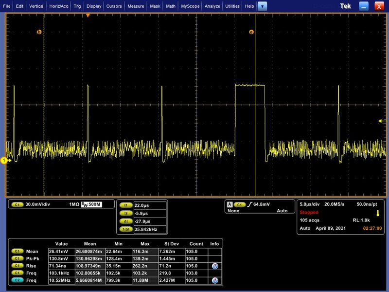
There is no image when we run the camera capture examples for case 2, case 3. (And no error either.)

We measured the MIPI clk and believe set the correct data rate. still no luck. 

Please, how can we figure out the cause of the problem? which registers do we need to check?  Is there a procedure we can follow to debug?

  • Hi,

    Can you first check the PHY_STATUS register and confirm that value in this register is changing when read multiple times? 

    Lets first try bringup #3, as it looks similar to #1, only deserializer is changed.

    In this case, are you sure that deserializer is streaming out data.. Is there a status register that you could check to confirm this? 

    Also when do you enable/start streaming in the dserializer? 

    Regards,

    Brijesh

  • Thank you for your reply. I think I solved case 2. in Max9286, I did not set the virtual channel number correctly. Once I correct the settings, I got the image to display on the screen. 4 camera images overlap and adjust to show full screen.  Does the multi-cam example support showing images from cameras side by side on the screen?

    I will check case 3 and update with you on the latest findings.

  • Hi,

    multi-cam examples down scales the input image to 1/4th of 1080p resolution and then merges all 4 cameras into single frame and displays. So it support 2x2 mosaic, does not support side by side display. But it can be easily changed, it just requires change in mosaic nodes configuration.

    Regards,

    Brijesh

  • Yes, the enable_mosaic is set to be disabled (enable_mosaic = 1) when the input image is YUV. I try to enable it manually, there is an error print out:

    [MCU2_0]    631.669919 s:  VX_ZONE_ERROR:[tivxKernelImgMosaicMscDrvSubmit:978] Failed to Submit Request

    and there is no image on the screen. What need I do to enable 2*2 mosaic display to YUV camera?

  • Hi,

    If you are connecting directly capture output to mosaic, then it would not be possible. Because YUV422 format is not supported in mosaic node. You need to convert YUV422 format to YUV420 using other node and then can be used in mosaic node.

    Regards,

    Brijesh

  • OK, got it. we will add a node to do that.

    Back to case 3, as we read the DPHY_STATUS register (0x04514048, we use CSI2_1 in this case), it returns 0x00333306.

    Other register values for your reference:

    (all under the condition that normal MIPI signal is measured on CSIRX pins. We connect des-max9296 to CSIRX_1, so its instance number is 1, instead of 0 by default.)

    Reg: 0x04514040 = 0x0001f01f  (enabled but still in reset state)

    Reg: 0x04514060 = 0x20000000  / 0x10000000  (payload)   value changes when poll continuously.

    Reg: 0x04514074 = 0x00000000 

    Reg: 0x04514080 = 0x00000000

    CSI_RX_IF_VBUS2APB_STREAM0_STATUS  0x04514104 = 0x80000113

    CSI_RX_IF_VBUS2APB_ASF_INT_STATUS  0x04514900 = 0x00000000

    CSI_RX_IF_VBUS2APB_DEVICE_CONFIG  0x04514000 = 0x8421164C

    CSI_RX_IF_VBUS2APB_STATIC_CFG Register  0x04514008 = 0x43210410  (the bits 1:0 is SEL, selection of DPHY used as input of CSI2RX module)

    I also attached the capture configuration code:

        if(vx_false_e == yuv_cam_input)
        {
            raw_image = tivxCreateRawImage(obj->context, &sensorParams.sensorInfo.raw_params);
    
            /* allocate Input and Output refs, multiple refs created to allow pipelining of graph */
            for(buf_id=0; buf_id<obj->num_cap_buf; buf_id++)
            {
                if(status == VX_SUCCESS)
                {
                    obj->cap_frames[buf_id] = vxCreateObjectArray(obj->context, (vx_reference)raw_image, num_capture_frames);
                    status = vxGetStatus((vx_reference) obj->cap_frames[buf_id]);
                }
            }
        }
        else
        {
            capt_yuv_image = vxCreateImage(
                                    obj->context, 
                                    sensorParams.sensorInfo.raw_params.width, 
                                    sensorParams.sensorInfo.raw_params.height, 
                                    //VX_DF_IMAGE_YUYV
                                    VX_DF_IMAGE_UYVY
                             );
    
            /* allocate Input and Output refs, multiple refs created to allow pipelining of graph */
            for(buf_id=0; buf_id<obj->num_cap_buf; buf_id++)
            {
                if(status == VX_SUCCESS)
                {
                    obj->cap_frames[buf_id] = vxCreateObjectArray(obj->context, (vx_reference)capt_yuv_image, num_capture_frames);
                    status = vxGetStatus((vx_reference) obj->cap_frames[buf_id]);
                }
    
                if(status == 0)
                {
                    APP_PRINTF("create ref ok");
                }
            }
        }
    
        /* Config initialization */
        tivx_capture_params_init(&local_capture_config);
        local_capture_config.numInst                                    = 1U;
        local_capture_config.numCh                                      = 1U;
        local_capture_config.instId[CAPT_INST_ID]                       = 1; //use instance 1 for DMS and front camera
        local_capture_config.instCfg[CAPT_INST_ID].enableCsiv2p0Support = (uint32_t)vx_true_e;
        local_capture_config.instCfg[CAPT_INST_ID].numDataLanes         =
                                                    sensorParams.sensorInfo.numDataLanes;
    
        local_capture_config.timeout = 33;
        local_capture_config.timeoutInitial = 500; 
    
    
        APP_PRINTF("local_capture_config.numDataLanes = %d \n", local_capture_config.instCfg[CAPT_INST_ID].numDataLanes);
    
        for (loopCnt = 0U ;
             loopCnt < local_capture_config.instCfg[CAPT_INST_ID].numDataLanes ;
             loopCnt++)
        {
            local_capture_config.instCfg[CAPT_INST_ID].dataLanesMap[loopCnt] = sensorParams.sensorInfo.dataLanesMap[loopCnt];
            APP_PRINTF("local_capture_config.dataLanesMap[%d] = %d \n",
                        loopCnt,
                        local_capture_config.instCfg[CAPT_INST_ID].dataLanesMap[loopCnt]);
        }
    
        local_capture_config.instCfg[CAPT_INST_ID].laneBandSpeed = 
        TIVX_CAPTURE_LANE_BAND_SPEED_560_TO_640_MBPS;  //for 9296 fix bandrate.
        //TIVX_CAPTURE_LANE_BAND_SPEED_120_TO_160_MBPS; // for ov10640, 720p surround-view camera.
        
        // TIVX_CAPTURE_LANE_BAND_SPEED_160_TO_200_MBPS;  // for MARS-ar0231, 
        local_capture_config.chInstMap[CAPT_INST_ID] = 1;
        
        capture_config = vxCreateUserDataObject(obj->context, capture_user_data_object_name, sizeof(tivx_capture_params_t), &local_capture_config);
        APP_PRINTF("capture_config = 0x%p \n", capture_config);
    
        APP_PRINTF("Creating capture node \n");
        obj->capture_node = tivxCaptureNode(obj->graph, capture_config, obj->cap_frames[0]);
        APP_PRINTF("obj->capture_node = 0x%p \n", obj->capture_node);
    
        if(status == VX_SUCCESS)
        {
            status = vxReleaseUserDataObject(&capture_config);
        }
    
        if(status == VX_SUCCESS) 
        {
            status = vxSetNodeTarget(obj->capture_node, VX_TARGET_STRING, TIVX_TARGET_CAPTURE1);
        }
    

    The mipi signal , clock rate is 300MHz.

  • For case 3, we can measure mipi signal on CSIRX pins. 

    And we only enable streaming when streamon callback is called in TI camera driver framework.

  • Hi,

    Register settings looks fine. Can you try refreshing PHY_STATUS register few times and see if its value is changing? That means PHY is detecting change in lane status.

    Apart from it, can you check if the data type and virtual channel id are correct? It should match exactly with the deserializer output. Otherwise CSIRX will not capture frames. 

    Rgds,

    Brijesh

  • Yes, it changes to 0x00222206 and then back to 0x00333306 alternatively. 

  • That means CSIRX does detect change in the lane status.

    Could you please check if data type and virtual channel id are exactly matching? 

    Rgds,

    Brijesh

  • We just have a big step forward. After change virtual channel number settings (max9296), we can capture images using single cam example. but the color is not correct.

    It is not the display problem we met before(case by YUYV/UYVY data format). we can not upload an attachment currently, we will send you one hope you can help us to figure out where the problem is.

  • I just send the image to you with a private message. Thank you.

  • Sure, please zip the file and attach it this post.

    Rgds,

    Brijesh