This thread has been locked.

If you have a related question, please click the "Ask a related question" button in the top right corner. The newly created question will be automatically linked to this question.

TRF370417: Leading or Lagging

Part Number: TRF370417

Hello E2E,

For the TRF370417 modulator, does the in-phase LO lead or lag the quadrature LO?  Is there a universally accepted convention for this and what are the implications of the transmitter and receiver using opposite relationships?

Regards,
Carlo

  • Hi Carlo,

    The answer to your question will depend on your final RF placement with respect to the LO. The phase relationship is relative. It is best for you to understand and work out the complex Euler's equation yourself, step by step, to understand the meaning behind the equations. You may refer to training document below. 

    https://training.ti.com/sites/default/files/docs/TIPL4708%20-%20Real%20and%20Complex%20Modulation.pdf

    The universally accepted convention should be the equations (baseband equivalent and bandpass equivalent notations) that are highlighted in the training document above, page 3 and onwards. 

    -Kang

  • Hello Kang,

    Our customer has a follow-up questions as follows:

    Since I can't change the LO relationship (it's dictated by the IQ modulator internals) and I don't even know what it is (it's not documented), how can I change the LO lead or lag depending on where I want to place the final RF signal? Again, I am not asking about the I and Q signals.

    I understand Euler's Equation.

    If y(t) is IQ modulator output where w is the LO frequency, then we want:

    y(t) = Re[ ( I(t) + jQ(t) ) * e^(jwt) ] = I(t)*cos(wt) - Q(t)*sin(wt)

    Notice the minus sign.

    If we want this to match

    y(t) = A*cos(wt + phi)

    where phi is the phase angle of the IQ phasor, then the LO signals that mix with I(t) and Q(t) must be such that the I-LO lags the Q-LO -- due to that minus sign! Which means that if cos(wt) mixes with I(t), that -sin(wt) must mix with Q(t).

    However, a large fraction of the diagrams found on many websites, including courses taught by such places as MIT, show the opposite. I am asking what the relationship is for TI's IQ modulators.

    Thank you for the assistance.


    Regards,
    Carlo

  • Hi Carlo,

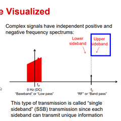
    the equation here shows upper sideband upconversion. This means if the baseband gets upconverted to LO's right side

    y(t) = Re[ ( I(t) + jQ(t) ) * e^(jwt) ] = I(t)*cos(wt) - Q(t)*sin(wt)

    if the minus sign below becomes a positive sign

    y(t) = Re[ ( I(t) - jQ(t) ) * e^(jwt) ] = I(t)*cos(wt) + Q(t)*sin(wt)

    then the upconversion is a lower sideband.

    I am not quite familiar with lead/lag terminology. If the customer can clarify which equation in his/her mind is lead, and which is lag, I would greatly appreciate his/her support.

    The equation I have in my Proakis text book shows negative sign for upconversion.

    www.gaussianwaves.com/.../