Hi,
Our customer have two questions.
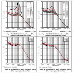
1 Is there a spec for the output jitter of the internal PLL (including VCO)?
Also, is there a way to calculate jitter?
2. If we set the same data for two outputs and start sending,
Will there be a time lag (Tskew) in the output data between Vout1 and Vout2?
If it does occur, please let us know the specifications.
Also, the time lag (Tskew) is
・ Even if the power is turned off and on, if the settings are the same, is the time lag fixed?
・ If the settings are changed, will the time lag change?
It may be nonsense to ask for specs, but in that case it would be helpful if you could give me some advice.
Regards,
Hiroshi