This thread has been locked.

If you have a related question, please click the "Ask a related question" button in the top right corner. The newly created question will be automatically linked to this question.

LMX8410LEVM: EVM and Voltage gain abnormal phenomenon

Part Number: LMX8410LEVM
Other Parts Discussed in Thread: LMX8410L

Hello,

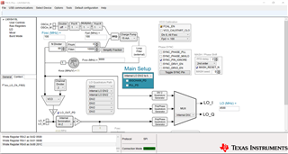
We're currently testing the LMX8410L evaluation module.
EVM and Voltage gain abnormal phenomenon need to be resolved.

Here is our testing environment: 
Signal generator : Keysight VXG M9384B
Mixed Signal Oscilloscope : Keysight MXR608A

We measured EVM and channel power on LMX8410L evaluation module at 4.5GHz LO with a 100MHz wide 64QAM 5GNR RF signal.
We inject RF power -15dBm from signal generator to RFIN(J11),
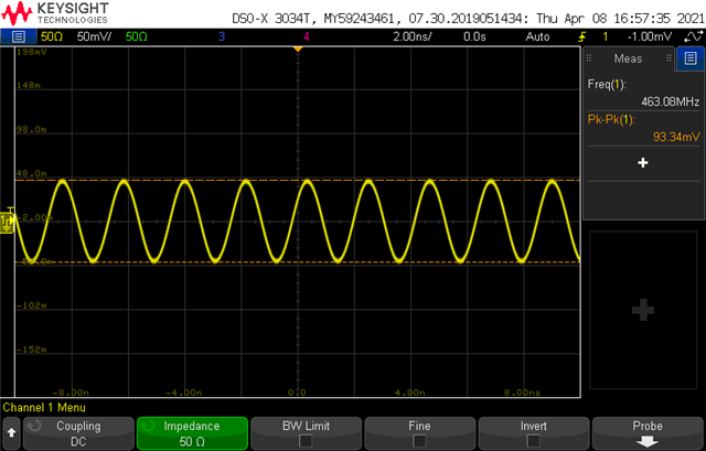
and connected IF-QP to Oscilloscope channel 1,IF-IP to Oscilloscope channel 2.(single-ended)
We get 5.676% of EVM and -17.52 dBm of channel power. (shown below)
The gain we measured is very different from data sheets typical gain 11dB at 4GHz and 5GHz.


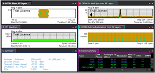
How can we get a better EVM and the voltage gain close to the data sheet?

Thanks a lots.
Alan Ke

  • Hi Alan,

    With the gain you're getting, it almost seems like the LO is not properly connected internally, which could be a result of a register configuration issue. Can I get the register programming for this measurement?

    Regards,

    Derek Payne

  • Hi Derek,

    Thanks for your reply,

    TICSpro configuration is shown as below.

    We only changed LO frequency, other setting remained default.
    Just in case, I also attach the register programming file(.tcs) 

    We did uncheck the LO_OUT_PD option and make sure that the current is normal.
    By the way,
    we put two 50 Ohm pull-up resistors at the positions of R54 and R55 to see the output of internal synthesizer.
    What configurations we need to set to get the voltage close to the data sheet?


    Best regards,
    Alan Ke


    LMX8410LEVM_register_programming.tcs

  • Alan,

    Thanks for uploading the register programming. It looks like the LO path is configured correctly, but I do see a few things that might have some effect:

    • It looks like you're using an integer divide with the synthesizer feedback path, so unless you intend to use the MASH_SEED to adjust the phase of the LO, the internal LO can be configured for integer MASH order instead. This eliminates potential synthesizer issues created by an unnecessary fractional divide.
    • The mixer page has incorrect values for IFA_PULLUP and IFA_CONFIG for a 1.7V VCM. Please update the settings as appropriate for 1.7V according to Table 2 in the datasheet. The IF amplifier VCMs need to be properly biased, or else the channel may not drive properly. (I note that the latest release has an outdated default mode which sets these values improperly as well; we have noted this and will update it in a subsequent release.)

    If the above steps do not improve issues, what do the results look like if the signal generator power is set to -10dBm? I don't believe there should be a large gap between -10dBm and -15dBm for RF input power, but it's quick to check.

    Regards,

    Derek Payne

  • Hi Derek,

    Thanks for your reply,
    I have solved the EVM issue which was caused by our testing instrument.
    But the voltage gain issue still remain unsolved.

    Could you be more specific at first point you mentioned above?
    How to set the internal LO to be configured for integer MASH order and what is MASH_SEED mean?

    At the second point, I updated the 1.7V VCM setting at the Mixer page according to the Table.2  in datasheet.
    Also, I supplied  external 1.7V VCM but it still didn't improve the gain result.
    When we the signal generator input power to -10 dBm then we get -13.72 dBm channel power.

    Finally, we have another question.
    For the system requirement, 

    we intend to use external LO at 4.5GHz to the Mixer and
    set the internal LO frequency at another frequency as output to supply other circuit moudle at the same time.
    W
    e found that there are two LO Paths can be set on the software(LO page)
    so we set one to be Internal LO DIV 2 and the other to be External LO.
    Is there any suggestion or command that you can provide?

    Thank you!
    Best regards,
    Alan Ke

  • Alan,

    Apologies for the delay:

    • Integer mash is set on the LO page, on the box that says "MASH / Phase Shift". The second box from the top (MASH_ORDER in the context window when you mouse over it) chooses the MultistAge noise SHaping (MASH) function; this amounts to the fractional randomization sequence used by the N-divider. Since you are using 100MHz OSCin and 9GHz VCO, you have an integer divide and could conceivably use an integer MASH order (no dithering required). Enabling the fractional randomization can add spurs which may make PLL lock more difficult, so I want to check if going to an integer MASH (effectively removing the MASH from the divider feedback) causes any improvement in the voltage gain.
    • MASH seed is at the bottom of the "MASH / Phase Shift" box on the LO page. This effectively chooses where the randomization pattern begins, and can be used to establish a phase offset at the output with respect to the OSCin input. This can be used for multi-device phase shaping when OSCin is the same phase across multiple LMX8410L. MASH seed usage requires the MASH order to be greater than integer, so if you are planning to adjust the internal LO phase you will need to use the MASH_SEED.
    • External LO can only go through the polyphase quadrature generator; there's no path for external LO to go through the divide-by-2 I/Q generator. Additionally, the external LO path can be input or output, but not both at once; I'm not sure if I understood what you want to do correctly, but it isn't possible to supply the internal LO as an output to another IC while using the external LO as an input to the mixer.

    I'm still uncertain why your voltage gain is so much lower than expected... just to confirm, you are driving the IF output into a 50Ω single-ended (100Ω differential) impedance, correct?

    Regards,

    Derek Payne

  • Hi Derek,

    Thanks for your reply.
    The third point you reply had solved our problem, but it still remained abnormal phenomenon of voltage gain.
    I actually switched  into integer MASH but it didn't have any improvement.
    About voltage gain calculation , I found another article in forum:
    https://e2e.ti.com/support/rf-microwave/f/rf-microwave-forum/692578/trf371109-gain-formula
    I referred to this article and try to recheck voltage gain.
    We injected RF power -10dBm(70mV RMS (50 Ohm))from signal generator to RFIN(J11),
    and connected IF-QP to Oscilloscope channel 1(single-ended).
    The results show as below.
      
    With 50 Ohm input impedence ,
    we got 93mV(peak-to-peak voltage) which equals to 33mV RMS and power -18 dBm.
    According to this result, IF output voltage is smaller than RF input voltage.
    Is this calculation formula correct or is there any suggestion you can provide?

    Thank you!
    Best regards,
    Alan

  • Alan,

    33mV RMS is about -16.5dBm (33mVpk is -18dBm); nevertheless, this is well below the expected 223mV RMS (632mVpp) which I would expect from the voltage gain. Nevertheless, it looks like the mixer is downconverting as expected. I checked your programming and didn't see anything else that would explain the low voltage gain. 

    Have you bypassed the onboard LDO? If not, have you confirmed that the 5V supply is at nominal voltage? If the integrated LNA was not receiving 5V, this could reduce the gain.

    The only other cause I could imagine is potentially a soldering issue or a signal integrity issue at the RF input trace. If you push down on the device package near the RF input, do you see any improvement? Does the C1 capacitor look aligned properly on the pads?

    Regards,

    Derek Payne