This thread has been locked.

If you have a related question, please click the "Ask a related question" button in the top right corner. The newly created question will be automatically linked to this question.

LMX8410LEVM: I/Q channels are not 180 degrees out of phase

Other Parts Discussed in Thread: LMX8410LEVM

Greetings, 

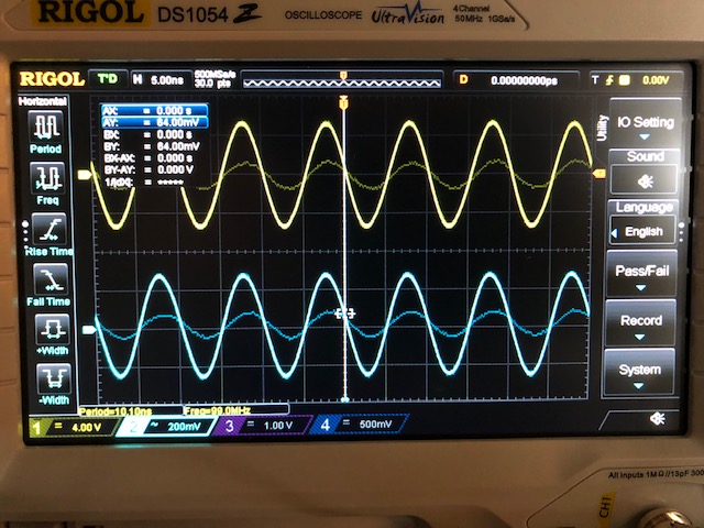
I am using the I/Q demodulator evaluation board. I've followed the helpful LMX8410LEVM Walkthrough video to setup and test the device. Everything works fine except the I/Q channels are not 180 degrees out of phase.

Hoping I am just missing something simple. 

Many thanks in advance,

-A

  • Hi Andrew,
    Could you share TICS Pro configuration file (save as .tcs) and your test result about "not 180 degrees out of phase"?
    Our expert would help to analyze it.

    Regards,
    Shawn
  • Shawn,

    Thanks so much for the response.

    Certainly -- attached is an image of the I/Q readings on the oscilloscope.

    What is the best way to attach the .tcs file? When I insert and try and send it I get an error message saying the file type is not supported.

    With regards to the TICS Pro configuration settings, I've tried toggling the MASH seed value as this it related to the phase shift, but it didn't seem to have any effect. I did notice that there are two 'default configurations' for this device, and neither seems to be the same as the one from the online video, so maybe the error has something to do with this. 

    Please let me know if you have any questions.

    Thanks again,

    -A

  • Andrew,

    The video was made for the pre-release product, and we made some adjustments for the final release. Please load the latest default setup in Ticspro. Make sure that the green light on the EVM is on, because it indicates that the internal PLL is locked. The outputs should be good if the PLL is locked. 

    The phase difference between I and Q channel should be 90 deg, and I think by 180 deg you mean the phase difference between differential outputs. Anyways, if you are using the internal synthesizer as LO, please make sure that the green light on before looking at results.

    Also, the use's guide is up to date. You can refer to that for more details. Let me know if the problem is still unsolved.

    Regards,

    Hao

  • Hao,

    Thanks very much for the helpful response.

    I re-ran the experiments. Attached are some images of the test setup and their corresponding results. The input voltage is 5.3 Volts and the current is 770 mAmps. The green light indicating the PLL is locked is on each of the two test setups.

    I had initially tried to replicate the 180 degree phase shift results when channel 1 and channel 2 cables of the Oscope are connected to the IF_IP and IF_IM, as described in the video. I can't seem to reproduce these results, and if several things have changed since the release of the video maybe I should have expected different results.

    If I connect the IF_IM cable to the IF_QP I get the expected 90 degree phase shift on the output.

    I had checked out the user's guide but there is no mention of expected results for the different cable configurations, so I am just trying to make sure it is working correctly. Hence my reference to the video. If this all looks correct to you then I am good to go. 

    Many thanks again for the help,

    Andrew

  • Andrew, 

    You're welcome.

    I haven't seen this before and cannot think of possible reasons for now. I may need more inputs.

    What is the RF frequency and LO frequency for your previous setup? Just for sanity check,  can you please set the LO frequency to 4000MHz (in Ticpro, after loading default) and set the signal generator for RF input to 4020MHz and -10dBm?

    After setting up frequency, please connect the four outputs IF_IP, IF_IM, IF_QP and IF_QM to channel 1, 2, 3, 4 respectively and check the results.

    The voltage and current consumption are correct and the board should be working correctly. Something else may be missing here.

    Regards,
    Hao

  • Hi Hao,

    Thanks for the response and thoughtful suggestions. I will look into them and be in touch.

    For my previous setup the RF input frequency was 5100 MHz and the LO frequency was 5000 MHz -- I was just following what was used in the video.

    Thanks again,

    Andrew
  • Andrew,

    No problem.

    Regards,
    Hao