This thread has been locked.

If you have a related question, please click the "Ask a related question" button in the top right corner. The newly created question will be automatically linked to this question.

AFE7071: the image spectrum of AFE7071 RF output is very high

Part Number: AFE7071
Other Parts Discussed in Thread: LMX2581

i use AFE7071  in my design.  i use a 64Mhz crystal oscillator as DAC clock(convert to differential clock by a balun)  and

FPGA clock, the FPGA generate DAC data and use same oscillator with DAC. i set AFE7071 to single differential  DDR

clock mode, and make sure the DACCLKP rising edge latch the I data, and falling edge latch the Q data.

the LO is LMX2581, differential output to AFE7071 LO input, and the LO frequency is 640Mhz.

i generate a single tone  I/Q base band data.  disable the offset and QMC function, but the RF output image spectrum is 

very high, only about -10dbc to the main output spectrum.  

1   i enable the QMC function and adjust the phase and gain ,but can not get good result.

2  i change the LO input to single ended(disconnect the LO_N to LMX2581 and connect to a capacitor and resistor to gnd)

    the image spectrum decrease to -25dbc.

the sideband  suppression is far away from the value in datasheet

can anyone can help me to resolve this problem?  can i should check the LO , config register or other point? 

  • Hi user,

    We are looking into this. Will get back to you ASAP.

    Regards,

    Vijay

  • Hi,

    Are you sending complex data to the AFE7071. It sounds like you are sending real data ( I and Q data is same)  and hence the image is not getting suppressed. 

    Can you please send me the screen shot of the output signal?

    Regards,

    Neeraj 

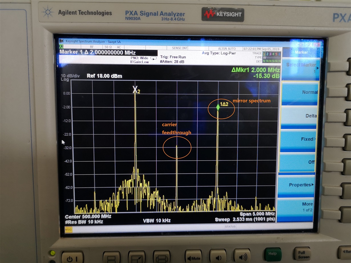
  • here is the output spectrum. i send i and q as complex data,  i = cos and q = sin,  i set the LO  output frequency to 500Mhz, and the output

    pull up conductor of LMX2581  to 50Ω resistor, the mirror spectrum decrease to about -15dbc。 i think the LO output will affect this. but 

    what should i check the LO signal? output level? sine wave or square wave? or other ...??? 

  • Hi Neeraj;

        I am a  FAE of  WPG chengdu.This problem is encountered by My client.My client is very urgent to deal with this problem.

       This client is Very important o for us. Could you please help to analyze it as soon as possible and give some Suggestions? Thank you!

  • Hello, 

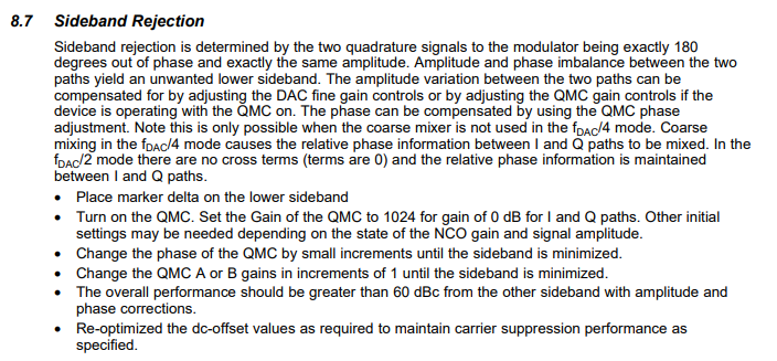
    Can you please verify that you have the "QMC enable" feature turned off? It is possible that you have it turned on unknowingly and therefore are using incorrect phase and gain values that cause the image to be higher than usual. Can you verify that QMC is disabled by programming the value 0x00 to the register address 0x05 and see if that makes a difference. 

    Thanks

    Yusuf

  • i have already check the "QMC enable" feature,  i compared turned off and turned on with qmc_offseta/b = 0,  qmc_gaina/b = 1024, qmc_phase = 0. 

    the output is same.  and i config qmc_phase = -512, the image spectrum decrease about 10db.   

    I have designed QMC phase adjust function in my FPGA design before data to AFE7071, and i find config the phase to a big offset value will minimize the image spectrum.

    so i think the phase imbalance of AFE7071 is very high and the range of QMC phase is limited. 

    the test result is as following table. i use QMC phase adjust in my FPGA design instead of AFE7071, and i use DC-offset and GAIN adjust feature by AFE7071, i can 

    get satisfying result, the carrier feedthrough and sideband suppression is below -60dbc, but i think the phase offset is very high at 300MHz and 500Mhz. 

    i want to know why? and how to resolve this problem? i don't want to adjust every produce carefully one by one.

    RF/L0
    frequency
    (MHz)
     
    I-offset value
    AFE7071 QMC
    Q-offset value
    AFE7071 QMC
    I-gain value
    AFE7071 QMC
    Q-gain value
    AFE7071 QMC
    QMC phase value
    AFE7071 QMC
    FPGA QMC phase value
    (-1024~+1023) means(-pi~+pi)
    carrier
    feedthrough
    after adjust(dBc)
    sideband
    suppression
    after adjust(dBc)
    100 46 4 1024 998 0 3 -81 -68
    300 48 1 1024 1024 0 -203 -74 -57
    500 51 1 1024 1026 0 -116 -73 -71
    700 52 1 1024 1025 0 -44 -75 -62
    900 55 1 1024 1026 0 -30 -82 -63
  • Hey User, 

    I will have to reach out to the designers of this part to receive insight in regards to your question. I will get back to you asap. 

    Yusuf

  • Hi Yusuf,  is there any progress? Thanks!

  • Hey User,

    My suggestion would be to manually program the QMC values through the AFE7071 and see if that helps. Please reference the following guide when determine QMC values. 

    Thanks

    Yusuf

  • thanks for your help. but i did many test and found that the LO itself will affect the sideband rejection.

    i tested the EVM board of AFE707X, use external LO, if the LO is sine wave signal, the sideband rejection

    performance is match the value in datasheet(-35dbc to 040dbc), but if the LO is square wave signal

    the sideband rejection performance will decrease to not more than -20dbc.  i want to know what's the 

    requirement of the LO signal, i din't find more detailed information in the datasheet. does i must use 

    sine wave signal to get normal sideband rejection performance? it's very important for my design? 

    because i use LMX2581 as my LO source. it's can cover the  rang of 200Mhz~900Mhz.  but the output 

    is drived by a divider. so it's square wave output. can you give some advice to resolve it? 

    another question, the LO input for EVM is single-ended, to get better sideband rejection, the single-ended 

    or differential input, which is better?

  • User, 

    The higher order LO harmonic content from your square wave will directly and negatively impact side band suppression. Therefore using a filtered sine wave as the LO source is highly recommended. I would suggest posting on the LMX2581 forum to see if its possible to  generate a sine wave. if so requrest that they assist you. 

    Yusuf