This thread has been locked.

If you have a related question, please click the "Ask a related question" button in the top right corner. The newly created question will be automatically linked to this question.

LMX8410L: phase synchronization

Part Number: LMX8410L

Hi team,

My customer has the following questions about lmx8410, and I am not familiar with RF. Please help me. Thank you in advance.

Use two lmx8410 evaluation boards.

OSCin  50MHz

LO        4860MHz

RFin     4800MHz

IFout   60MHz

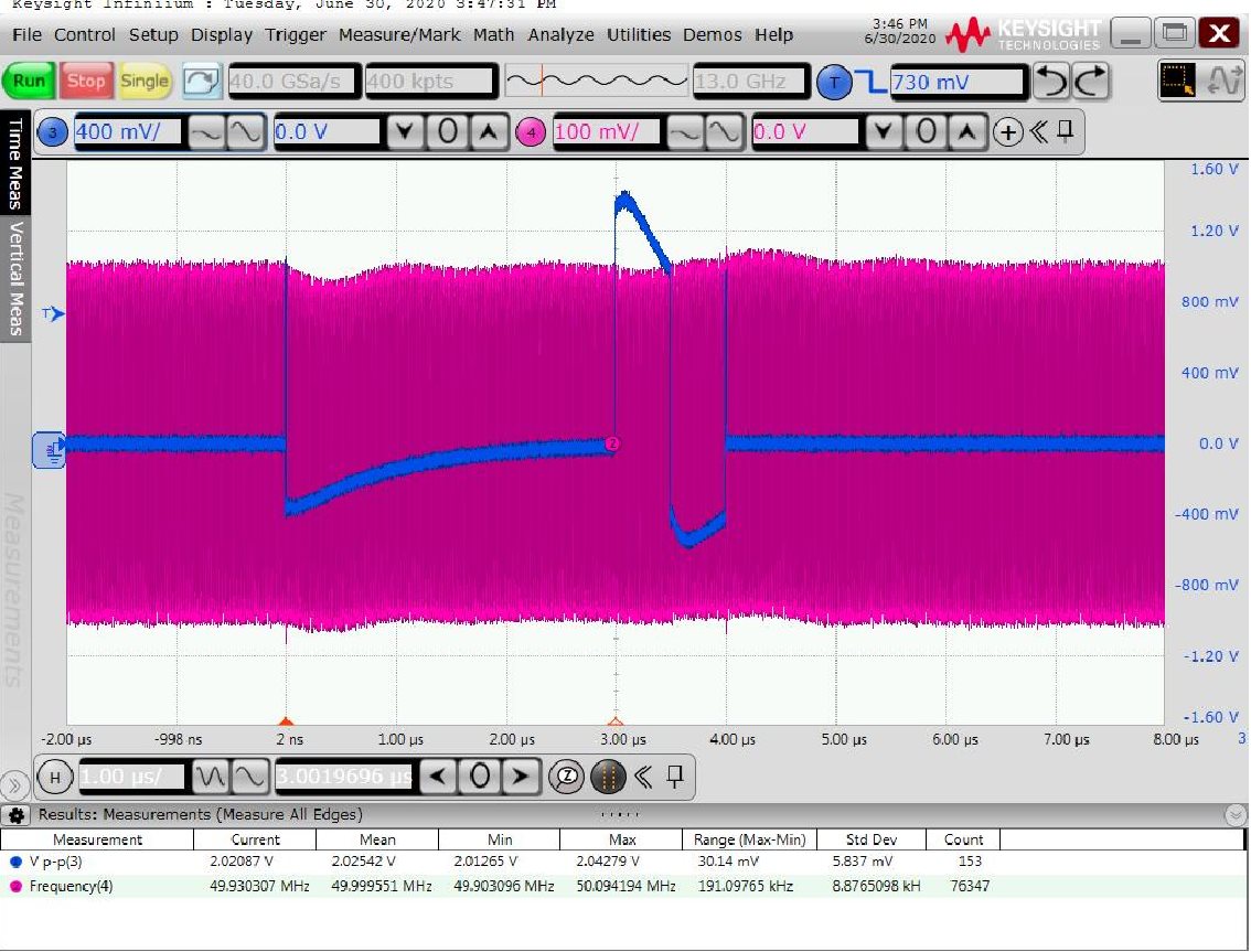
SYNC is 10MHz discontinuous pulse signalwhat is the format of sync signal?

The OSCin, RFin ,and SYNC are synchronous, and the SYNC pulse signal is triggered manually outside, and the phase synchronization cannot be carried out. What are the specific software and hardware implementation steps to achieve the phase synchronization?

Note: both OSCin and SYNC are synchronization signals provided by external HMC7044.

Best Regards,
Amy Luo


  • Hello Amy,

    The SYNC pin is an input pin. A square pulse, with a strong slew rate / rising edge would be recommended. Please ensure you meet voltage levels mentioned in the datasheet under "DIGITAL INTERFACE (SCK, SDI, CSB, MUXOUT, SYNC, CE)" section of "Electrical Characteristics".

    For cases where the LO output frequency is not a multiple of the input frequency, such as yours the SYNC pin must be used and the timing must be away from the rising edge of the OSCin signal. You will also need to ensure that the SYNC timing meets the setup and hold time for the SYNC pin listed in "6.6 Timing Requirements" section.

    Thanks,

    Vibhu

  • Hi Vibhu,

    Thank you very much.

    Now, the two signals can be synchronized occasionally, but many times after the SYNC pulse is sent, the phase difference is very large. Referring to your suggestions, the customer has made the following analysis:

    1、

    As shown in the figure, the distance between the rising edge of SYNC and the rising edge of OSCin is at least 3 ns, which should be satisfied.

    Secondly, the duration of high level reaches us level, which should also satisfy tHOLD.

    About tSETUP you mentioned, I can't understand it. Can you explain it in detail?

    2. The waveform of SYNC signal is shown in the following figure:

    The red waveform is OSCin, and the blue is SYNC pulse. Observing the SYNC signal, we can see that there is a burr of about 950mv in front of and behind of the pulse signal. Does this make LMX8410 mistakenly identify as SYNC pulse and produce wrong synchronization?

    Warm regards,
    Amy 

  • Hello Amy,

    The setup time is the time SYNC must be high before OSCin goes high. I would not think the blip is causing the issue, however would you be able to try using a difference SYNC source to narrow down the issue.

    Thanks,

    Vibhu