This thread has been locked.

If you have a related question, please click the "Ask a related question" button in the top right corner. The newly created question will be automatically linked to this question.

DETECTING RF SIGNAL FROM GSM MOBILES USING LM358

Part Number: LM358

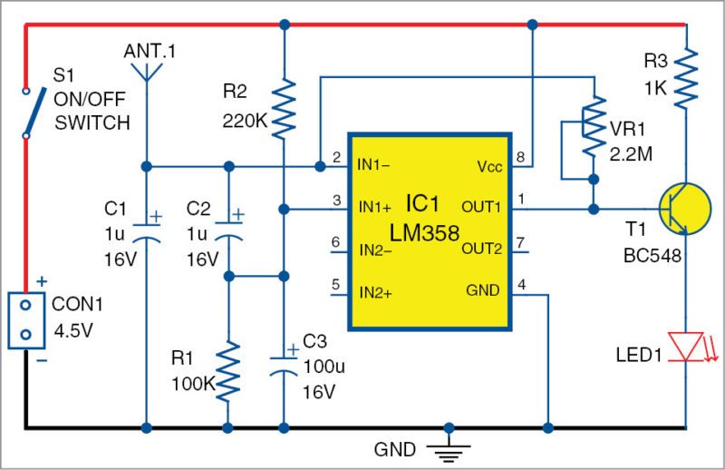
CAN SOMEONE EXPLAIN HOW THIS CIRCUIT WORKS AND WHAT EQUATIONS WHERE USED TO CALCULATE THE VALUES OF RESISTORS AND CAPACITORS.

  • John,

    This is an inverting amplifier with a gain set very high. Basically 2.2M / ESR[C1] .  ESR is the cap's resistance. 

    DC operating point IN1+ and OUT1 are set by a voltage divider. Jumping to conclusion 3.1V

    3.1V at output lightly turns on voltage drops of T1 and LED1, so any signal could turn LED on brighter

    At GSM frequencies the input cap C1 will actually appear to be inductive (past self resonance); so it is high impedance to GSM and a low impedance to 50/60Hz line 

    LM358 is not great at EMI rejection and the GSM creates a DC error that could raise the DC output which turns the LED brighter.

    R3 limits the maximum LED current

  • Thank you for your answer . If you have time can you provide insight on the design equations used to calculate the values of the resistors and capacitors.

  • You meant that the transistor acts as a switch right.

  • Voltage at pin 3 = V * R1 / (R1+R2)

    Capacitor values are not critical. Like I said at GSM frequencies they do not act like capacitor's any more. At 50 or 60Hz the captative reactance will be low compared to resistors. Xc=1/6.28/F/C  F=frequency, C = capacitance

    T1 is a voltage follower , emitter output voltage = (base input voltage) - (base emitter drop voltage).

    The base emitter voltage is a function of temperature and logarithm of collector current. Roughly 0.6V

  • Thank you for your answer