This thread has been locked.

If you have a related question, please click the "Ask a related question" button in the top right corner. The newly created question will be automatically linked to this question.

AFE7444EVM: LED D7 LMK LOCKED doesn't light up after set mode

Part Number: AFE7444EVM
Other Parts Discussed in Thread: TSW14J57EVM, LMK04828, AFE7444

Hello,

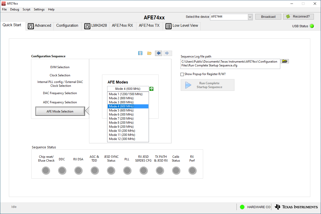
I would like to configure the AFE7444EVM in mode 4 using the internal mode.

My configuration is identical to the videos as well as the User Guide. 

  • AFE74444EVM

  • DC power supply 5.5V 5A

  • sinusoidal 10MHz 1.9Vpp reference (on LMK CLK IN SMA connector)

  • mini USB cable from the kit

  • TSW14J57EVM

  • DC power supply 12V 3A

  • USB cable from the kit

The AFE7444EVM and TSW14J57EVM are connected to each other. The AFE7444EVM JP9 jumper is in position 2,3 (internal clock mode).

I have configured the TSW14J57EVM in mode 4 before the AFE74444EVM.

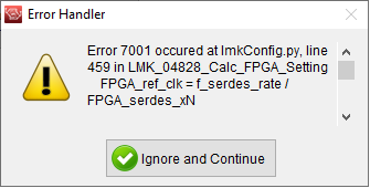
Thus, when applying mode 4 on the AFE7444EVM, its clock should be configured at the same time and therefore light up LED D7 (LMK LOCKED). However, this is not the case in our tests.

Also, when we select mode 4 for the AFE7444EVM, we are supposed to see, in the drop-down list, some modes grayed out meaning they are not selectable due to the DAC and ADC frequencies selected earlier. Here again, it is not, all the modes are selectable as if the software didn’t take into account our previous choices. The version of the AFE74xxGUI software that we have is 2.2.9.

Finally, when we set the TSW14J57EVM to mode 4, the TX SYNC LED doesn't light up, like in your videos, but if I turn off the AFE7444EVM, that same LED lights up as it should. The RX SYNC LED is actually on.

So here are my questions:

- Why does the D7 (LMK LOCKED) LED not light up after applying mode 4 to the AFE7444EVM?

- Is the 10MHz reference on the LMK CLK IN input really necessary for operation in internal mode?

- Why all modes are selectable despite the frequency preselection and does it have an impact on the wrong configuration of the clock?

- Why does the TX SYNC LED not light up after applying mode 4 on the TSW14J57EVM?

- Could I have the latest version of AFE74xx GUI software ?

- Could I have screenshots of your configuration in internal mode ?

- Why both inputs CLKin0 and CLKin1 are enabled when input 0 seems to be connected to nothing on the schematics ?

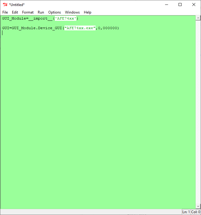
- Could you also provide an effective python configuration script ?


Thanks for your help.

Have a nice days.

William

  • Hi Willian,

    10Mhz input to LMK is optional when on-board clock generation is used. It can be used to lock on-board 122.88MHz crystal oscillator to external 10 MHz reference frequency. When "Set Mode" button is clicked, LED D7 turns on to indicate LMK PLL2 is locked. So it should light up irrespective of whether 10 MHz clock is connected or not. When 10 Mhz reference clock is connected, LED D6 should also light up  indicating that LMK PLL1 (on-board crystal) is locked to the 10MHz clock.

    Regarding the other questions, I will setup the EVM in lab and verify this and get back to you tomorrow. 

    Regards,

    Vijay

  • Hi Vijay,

    First of all, thank you very much for your quick answer.

    I continued to investigate in the meantime. I think part of my problem, is that reading registers from the AFE74xxEVM does not work, while writing does.

    To be sure, I decided to re-program the STATUS_LD1 and STATUS_LD2 outputs of LMK0482 in order to light up LEDs D6 and D7 respectively.

    According to the LMK0482 datasheet, by programming (via the Low Level View tab of the AFE74xx GUI) the registers 0x15F and 0x16E to the value 0x04, I observe that the LEDs light up. Reading gives me zero everytime, regardless of the state of the LED. I observe the same behavior from the Python script below;

    GUI_Module = __ import __ ('AFE74xx')

    GUI = GUI_Module.Device_GUI ("AFE74xx")

    GUI.write_register ("LMK04828", 0x016E, 0x04)

    val_ld1 = GUI.read_register ("LMK04828", 0x015F)

    val_ld2 = GUI.read_register ("LMK04828", 0x016E)

    print ("Status LED LD1 =% d"% val_ld1)

    print ("Status LED LD2 =% d"% val_ld2)

    Reading does not work either.

    And to put it simply, we can't read the version number, or any other registers.

    Even more surprising, by plugging a logic analyzer on the SPI bus connected to the LMK

    HTSW-104-07-G-T-.240, only the LMK_CS shows signs of life, whether writing or reading.

    Do you have any idea why reading isn’t working?

    Thank you again for your help.

    Have a nice day.

    William

  • Hi William,

    I have setup an AFE7444EVM and verified that when I click "Set Mode" button, LED D7 (LMK PLL2) lights up. Can you get this? (as you said SPI writes to LMK are working). I'm also able to read back chip ID (register 0x003 reads back value 0x06). 

    Also you say writing into LMK registers is working for you. But you don't see signal on LMK_SCLK and SDI when writing? 

    Regards,

    Vijay

  • Hi Vijay,

    As I told you before, when I press the Set Mode button, the LMK doesn’t seem to be program.

    I can confirm that I can write and read the evaluation board, but only, by switching both AFE7444 and LMK04828 to 4-wire SPI mode, instead of 3 by default.

    print '# Set LMK : 4 wires for SPI bus '
    GUI.write_register("LMK04828", 0x000, 0x10) #3 wire mode disabled
    GUI.write_register("LMK04828", 0x14a, 0x33)

    print '# Set AFE : 4 wires for SPI bus '
    GUI.write_register("AFE76xx_GLOBAL",0x00, 0x30)

    if False:
    val_r0 = GUI.read_register("AFE76xx_GLOBAL", 0x00)
    print("\t| Reading of AFE register 0x000: 0x%x (expected 0x030)" % val_r0)

    The python script "Example startup sequence.py" , properly configure the LMK after execution (leds D7 and D6 light up, as well as led PLLREFLD).

    It therefore seems that the problem came from the AFE74xx GUI software and the python scripts used.

    Can you send me the latest version of AFE74xx GUI software (and working pythons scripts) please ?

    Have a nice day.

    William

  • Hi William,

    GUI version 2.2.9 is the latest one. I have been testing with the same version. If you want to re-install to be sure, please download 'Setup_AFE74xx_EVM.exe' from AFE7444 secure folder (ti.com/mysecuresoftware).

    GUI is configured to use 4 wire mode for both LMK and AFE. So it is expected for SPI readback to work in 4 wire mode. 

    Regards,

    Vijay

  • Hi Vijay,

    As a reminder, the AFE74xxEVM is not defective. Interactions with the software are faulty. For this reason :


    - Can you send me a version of the software that has been verified to work?


    - Can you send me, at the same time, all the python scripts, also verified?


    - Can you send me the "startup_sequence_example" sequence with direct writing of registers in python, in an informed mode?

    Have a nice day.

    William

  • Hi William,

    Sorry for the delay in my reply due to Thanksgiving break. 

    GUI version 2.2.9 is the latest and has been verified to work. It has to be downloaded from a secure folder (ti.com/mysecuresoftware). If you don't have access to the folder, request access here: https://www.ti.com/licreg/docs/swlicexportcontrol.tsp?form_id=288371&prod_no=AFE7444&ref_url=asc_dc_hsc

    Python scripts are packaged into the GUI installer. Once GUI is installed, scripts will be in folder: C:\Program Files (x86)\Texas Instruments\AFE74xx\Python Scripts

    Sequence log file is auto-generated by GUI when "Run Complete Startup Sequence" button is clicked. This register log file can be used to program AFE on custom board (without using GUI).

    I attached a log file for Mode 6. This is not a python script but a register write sequence for AFE bringup.Run Complete Startup Sequence.cfg 

    Regards,

    Vijay

  • Hello Vijay,

    I reinstalled the software environment correctly, however my configuration of the card and more specifically of the LMK04828 does not work by using the AFE74xx software.

    This component is supposed to be configured after a SET MODE from the software, but it is not.

    I quote: “After you select the desired configuration mode, click Set Mode. Set Mode programs the onboard LMK04828 clocking chip. After set mode is complete, you should see the LED labeled LMK Lock on the AFE74xx-EVM go hot. This indicates that PLL loop two of the LMK chip is properly logged. ”

    Here are screenshots of my first configuration step in mode 6 and internal clock:

    As you can see, your software's recording window indicates that this SET MODE does not write or  read LMK04828 registers. The configuration of this component therefore doesn’t take place and I can’t continue configuring the card from the software.

    Can you help me to achieve a functional use of the software?

    Thank you for your understanding, any help is welcome.

    Regards,

    William

  • Hi William,

    I have to check this on an AFE7444EVM setup. I will check this in lab by the end of this week and get back to you.

    Regards,

    Vijay

  • Hi William,

    I have re-installed the software from secure folder to be sure and tested. When I click 'set mode', I see LMK writes in script window (after selecting 'start recording')

    So I don't suspect GUI has an issue. Many other customers successfully used this GUI version. Can you please double check if the installation happened without any errors? 

    Regards,

    Vijay

  • Hi,

    I have the same problem. Nothing happens after click in set Mode button in script windows. 

    My questions are :

    -  What OS do you use on your computer?

    - Why don't I have some modes in gray? (see screenshot below)

    Best regards,

    Thomas

  • Hi Thomas,

    Please find my answers below:

    -  What OS do you use on your computer?

    Vijay: Windows 10.

    - Why don't I have some modes in gray? (see screenshot below)

    Vijay: The screenshot you attached is not viewable. I'm assuming you are referring to mode selection as in the below screenshot. The GUI doesn't grey out modes based on "DAC Frequency Selection" or "ADCC Frequency Selection". User has to manually select the right mode. 

    Regards,

    Vijay

  • Hi Vijay,

    Thanks for your prompt response.

    First of all, sorry for the screenshot don't appear in my comment. The screenshot is exactly the one I wanted to put.

    To investigate the "set mode" problem, we put an oscilloscope on the SCK pin of the LMK (see screenshot below). We noticed no change in the SCK when pressing the "set mode" button. 

    Moreover, an error is displayed in the GUI after using the "set mode" (see screenshot below).

    The full message is as follows:

    Error 7001 occured at lmkConfig.py, line 459 in LMK_04828_Calc_FPGA_Setting
        FPGA_ref_clk = f_serdes_rate / FPGA_serdes_xN

    UnboundLocalError:  local variable 'FPGA_serdes_xN' referenced before assignment

    Call Chain:
    lmkConfig.py, line 459 in LMK_04828_Calc_FPGA_Setting
    -> lmkConfig.py, line 102 in LMK_Cnfg_Set_LMK04828
    -> GUI_Interface.py, line 185 in Wrapper_LMK_Cnfg


    Do you have any idea where this problem might come from?

    Thanks for your help.

    Best regards,

    Thomas


  • Hi Thomas,

    As you get an error when you click "set mode", this is a software issue. Looks like no SPI writes are going through. That's why you don't see any activity on SPI CLK.

    AFE74xxGUI uses labview runtime which is installed along with GUI. I suspect this might not have installed. Please uninstall GUI and reinstall it making sure that there is no error during installation. 

    Also please open GUI as administrator and try to program EVM. 

    Regards,

    Vijay

  • Hi Vijay,

    I verify and labview is installed along with GUI. I have installed and uninstalled several times, it still doesn't work. The screenshot below shows that the software has been installed correctly.

    I noticed another problem on the GUI in relation to the script window. I have a comma in the parameters and I saw in your previous screenshot that it was a dot. Wouldn't that be the problem? (see screenshot below) 

    Best Regards,

    Thomas

  • Hi Vijay,

    I didn't get any feedback from you on my last post.

    You have no idea where my problem could come from on the GUI of the AFE7444EVM board. I'm annoyed because the board is unusable at the moment.

    Thanks for your help.

    Best Regards,

    Thomas