This thread has been locked.

If you have a related question, please click the "Ask a related question" button in the top right corner. The newly created question will be automatically linked to this question.

TRF372017EVM: Suppressing harmonics

Part Number: TRF372017EVM
Other Parts Discussed in Thread: TRF372017

Hello team,

My customer is evaluating TRF372017EVM.

Could you please help me to suppress harmonic level so the RF target frequency 1201MHz is the higher than the harmonic level?

Ref frequency is 100.352 MHz. 

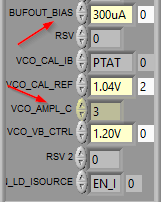
Please see the GUI display and harmonics levels from the internal link here

Undesired frequency component with 300MHz step can be seen. Could you please help me to  suppress this?

Also, the difference between the target frequency level 1202MHz and 2nd/3rd order harmonics levels are only approximately 3dB.

Regards,

Itoh

  • Hi Itoh-san,

    Do you have performance plots to help understanding the problem? If the TRF372017 is configured with internal LO drive, then you can try to increase the LO power going into the internal LO connection through BUF_BIAS and VCO amplitude registers.

  • Hi Itoh-san,

    I am awaiting your reply to further debug this. Thank you.

    -Kang

  • Hello Kang-san,

    I believe you can find the spectrum from the internal link attached at the first post. Please let me know if any missing plots you need.

    I'll check the BUF_BIAS and VCO amplitude registers with the customer.

    Please allow me to ask you one additional question.

    I observe 10MHz output (-29.52dBm) at RFOUT which is not desired in my system.

    Should it be OK? Is this leakage of I signal?

    I'd like to suppress 10MHz signal as my target frequency is 1200MHz.

    Is it possible to suppress the 10MHz component by changing device configuration?

    Regards,

    Itoh

  • Itoh-san,

    Please advise if there are any 10MHz routed to the TRF372017. Please advise the setup information for the TRF372017. The TRF372017 should not generate the 10MHz by itself. It may be externally coupled from either the power supply or external clocks. 

  • Hello Kang-san,

    Please find the internal link here for the measurement setup.

    10MHz comes from REF OCXO.

    Regards,

    Itoh

  • Hi Itoh-san,

    Is the 10MHz spur located at 10MHz at the TRF372017 output? or is it located 1200MHz +/-10MHz?

    The 10MHz of the REFOCXO is clocking the LMX device, not the TRF372017 directly. Therefore, if the TRF372017 has 10MHz output at the RF output, then it is something else. There could be some coupling due to RF or power supplies, and it is most likely located at 1200Mhz +/-10MHz. In both cases, the customer will need to revisit the layout to minimize any coupling of the 10MHz source to the TRF372017 by any PCB traces.

  • Hello Kang-san,

    The spur is located at 10MHz.

    Apologies I was missing to tell you one point. 10MHYz signal is input to I (J3 in EVM) at -16.55dBm.

    So the leakage from I part is suspected. As this issue is happening in EVM environment, I don't think the layout is the cause.

    But in any case the coupling due to RF or power should be concerned.

    Regards,

    Itoh

  • Hi Itoh-san,

    There will be some baseband leakage. However, the baseband signal is intended to be far away from RF, and therefore, the RF bandpass filter at the RF output should be designed to filter out the baseband signal.

    -Kang