This thread has been locked.

If you have a related question, please click the "Ask a related question" button in the top right corner. The newly created question will be automatically linked to this question.

TRF372017: Clock performance issue

Part Number: TRF372017

Hi Team,

My customer is evaluating TRF370217 EVM and has some issues that described as following. Please give us some advices.

We're currently testing the TRF372017 evaluation module.
EVM abnormal phenomenon need to be resolved.
Here were our testing environment:
Signal generator : Keysight VXG M9384B
Signal Analyzer : Keysight UXA N9040B
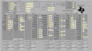
GUI setting(default):


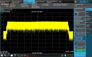
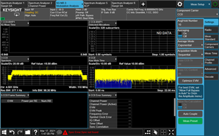
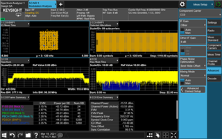
We measured EVM on TRF372017 evaluation board at 4.5GHz LO with a 100MHz wide 64QAM 5GNR baseband signal coming from signal generator.
There was a high peak in the middle, and we couldn’t get the EVM(shown below).


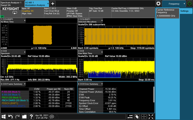
But once we switched the I/Q baseband input(IN←→QN,IP←→QP), the connection picture is as below.


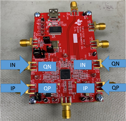
we can get the poor EVM while still existing a DC offset. (shown below)


From the above situation ,
How can we eliminate the DC offset and get excellent EVM?
Also, we want to know the reason why we have to switch the I/Q baseband signal to get the EVM result.


Thanks a lot.

Vincent Chen

  • Hi Vincent,

    for the DC offset, you may use the DC offset correction feature of the TRF372017. It is specified in section 7.3.13 of the datasheet. This is a iterative approach to reduce DC offset. 

    At the same time, the Keysight instrument should also offer some sort of carrier cancelation feature by adjust the DC offset, assuming you are DC coupled to the TRF372017.

    5G demodulation also can have features to ignore DC carrier. I am not familiar with Keysight software, but I know other customer have used Keysight software and disabled/ignored DC carrier in the demodulation.

    There are cases that Keysight generator requires I/Q swap. I/Q signal are 90 degrees relative to each other. The absolute phase relationship of I/Q may be different between instruments. I have heard customers saying they need to do I/Q swap on Keysight instrument, but not R&S instruments. Again, I/Q signal are relative to each other. As long as you are getting right demodulation, the relative relationship can be safely ignored. 

  • Hi Kang,

    I have replied to customer and will let you know if any other further question.

    Thanks a lot.

    Vincent Chen

  • Hi Kang,

    We measured EVM on TRF372017 evaluation board at 4.5GHz LO with a 400MHz wide 256QAM 5GNR baseband signal coming from signal generator.
    The results is shown as below.


    I tried to adjust the DC offset correction feature follow the section 7.3.13 of the datasheet but it still didn't improve EVM.
    On the other hand, I set "VREF_SEL" from 0.85 V to 0.65 V, "TX_DIV_BIAS" from 37.5uA to 50uA and "LO_DIV_BIAS" from 50uA to 62.5uA.
    It did improve the result of EVM but it still have a high EVM peak.
    Would there be any other affections to EVB performance by the parameters I set?
    Could you provide some suggestion about high EVM peak phenomenon?

    Thank you.
    Best regards,
    Alan Ke

  • Alan

    I tried to adjust the DC offset correction feature follow the section 7.3.13 of the datasheet but it still didn't improve EVM.

    Please advise if the DC offset had improved. You are ac coupling from the signal generator, so this feature is the only way to calibrate DC offset. You should see close to 80dBc of suppression. The setup is iterative, so you will have to try to adjust I side slow, and adjust Q side, and vice versa to get to good suppression.

    This is zero IF input from the signal generator, please check if you signal generator has ability to suppress the image. They should be able to adjust I/Q phase imbalance so you get low image power. You will need to shift the IF to -100MHz offset, for example, to observe the image power. This will help you with your EVM also.

    On the other hand, I set "VREF_SEL" from 0.85 V to 0.65 V, "TX_DIV_BIAS" from 37.5uA to 50uA and "LO_DIV_BIAS" from 50uA to 62.5uA.

    These are not DC offset correction registers. Please go through 7.3.13 again for Ioffset and Qoffset accordingly.