This thread has been locked.

If you have a related question, please click the "Ask a related question" button in the top right corner. The newly created question will be automatically linked to this question.

TRF372017: RF OUT Frequency range

Part Number: TRF372017
Other Parts Discussed in Thread: TRF370417, LMX2572, TRF3705,

Hi, I am planning to use TRF372017 IQ modulator to generate 4.5 GHz signal from base band I & Q signal.

Does this IC support up to 4.8 GHz signal generation?

LO Frequency range is given 300 MHz to 4.8 GHz. Does it means RF OUT(pin 18) shall be in that range?

In its data sheet i see in one of the typical application Ex, performance of TRF372017 in Table 29, RF OUT range mentioned is 300-4300 MHz!

  • The TRF372017 supports RF output to 4.8 GHz. The datasheet plots provide characterization data to 4.8 GHz. Table 29 is simply identifying a telecom example that operates up to 4.3 GHz; it is not a limit.

    --RJH
  • Hi RJH,

    Thank you for the info.

    We want to know what are all the frequency components (spurs or harmonics of reference if any) expected other than intended programmed RF OUT in TRF372017 in the span of (RF OUT± 100 MHz) and their levels for the below mentioned cases.

    I & Q : Base band signals with 10 mbps max. Any PRN sequence.

    LO programmed for 4.45 GHz.(RF OUT)

    Case 1: Reference frequency : 100 MHz

    Case 2: Reference frequency : 40 MHz

    --

    Regards,

    Raghu

  • Hey Raghu, 

    I took some measurements of the TRF3720's RF output generating a 4450M LO with a reference frequency of 38MHz, & 102MHz. Fin was 10MHz for both measurements. 

    Reference Freq = 102M

    1. Unadjusted SBS = -31.71 dBc

    2. Unadjusted CF = -31.48 dBm 

    4. PFD harmonic = -85dBc

    Green line shows -90dBc from carrier

    The rest are higher order harmonics of the input frequency. 

     .

    Reference = 38.4MHz

    4. Ref Harmonic = -85dBc

    Yusuf

  • Hi Yusuf,

    Thank you very much for the measurement.

    I hope these are the only signals which are prominent in the full span.

    I understand that we can minimize these CF by desired DC offset to IQ inputs and SB by IQ gain ratio and phase adjustment.

    We need at least 70 dBc at the RFOUT.

    Is it possible to suppress those unadjusted SBS and CF (basically all the signals which are less than 70 dBc) to 70 dBc min?

    If yes,to achieve it what are the things we need to take care in our design (like settings of DAC, TRF372017 if any, filter requirement for IQ inputs).

    Please also confirm, we understand from your measurements, for any REFERENCE frequency only PFD component is effected and it is always more than 80 dBc?

    Regards,

    Raghu

  • Hey Raghu, 

    Yes you should be able to suppress the CF & SBS spurs to below -70dBc by adjusting the offset gain and I/Q amplitude and phase respectively. As far as design recommendations for interfacing DAC's to I/Q modulators please reference the following reference design. 

    http://www.ti.com/lit/ug/slua647a/slua647a.pdf

    Yusuf

  • Hi Yusuf:
    Thank you for the info.
    For our another application we need BPSK modulation at 5 to 6 GHz. As TRF372017 does not support above 4.8 GHz, shall we replace TRF372017 with the 'LMX2572 and TRF370417' to generate and modulate signal 6 GHz?
    If yes, Is there anything to be taken in 'LMX2572 and TRF370417' combination to achieve the CF & SBS spurs to below -70dBc?
  • Hey Raghu,

    The TSW3085 EVM is a reference design that contains a dual channel DAC integrated with a TRF3705 RF modulator. I have attached the link to the product page below. Perhaps you can view the schematic as a general reference for good performance. Keep in mind that the common mode voltage for the TRF3704 & TRF3705 are different so I am not advising to copy the schematic exactly. Also, review the layout guidelines for both the LMX and the TRF3704 located towards the end of both respective data sheets.

    www.ti.com/.../TSW3085EVM

    Yusuf

  • Hi Yusuf,

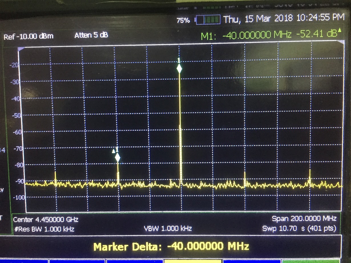
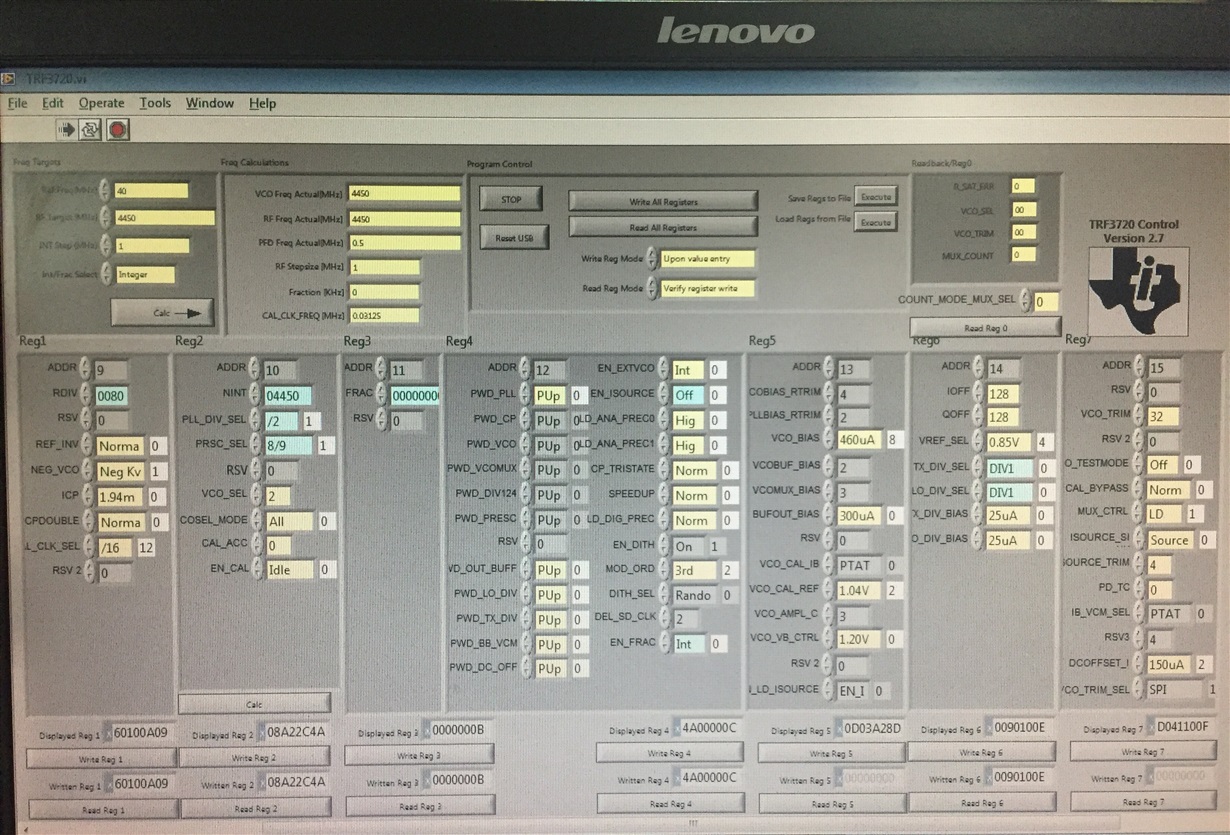
           We have received EVM. We are able to generate frequency 4450 MHz in integer mode faithfully as shown below

    For GUI settings

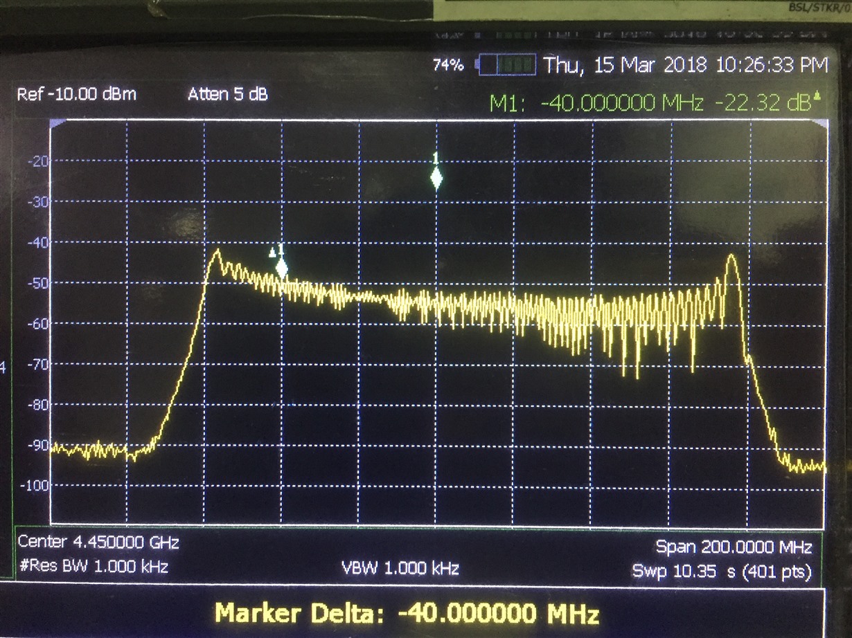
    But if i change integer mode to Fractional, i got the following output,

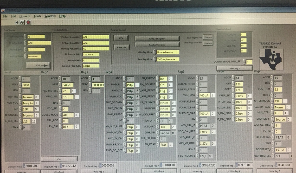
    GUI settings

    In fractional mode for any frequency entered in RF Target field, i am getting the above response centered around RF Target frequency(No lock indicator).

    Let me know is there any settings to be done in GUI to get proper locked signal in fractional mode.

    Set up:

    J4=J10 shorted J3=J9 shorted. No connection to these inputs.

    RF OUT measured through J6.

    Regards,

    Raghu

  • Hey Raghu, 

    Try increasing your INT step size to 20MHz

    Yusuf

  • Hi,

    What would be the cause of these spikes found at the center and at the nulls of the spectrum as shown below,

    This is observed in the TRF372017EVM.

    Thanks+Regards,

    Raghu

  • Hey Raghu,

    Did you try adjusting the IQ DC offset values in the GUI under register 5 and 6?
    Adjusting the DC offset of the baseband input signal wont matter since they are ac coupled you need to do it in the GUI.

    Yusuf