This thread has been locked.

If you have a related question, please click the "Ask a related question" button in the top right corner. The newly created question will be automatically linked to this question.

Lowest power capacitive sensor for rain?

Other Parts Discussed in Thread: MSP430FR2512, MSP430FR2633

Hi

I would need a really low power rain sensor in the range of <100uA's - checked the FDC familiy but it seems it is in range of 7-800uA-1 mA, at least the ones I've checked.

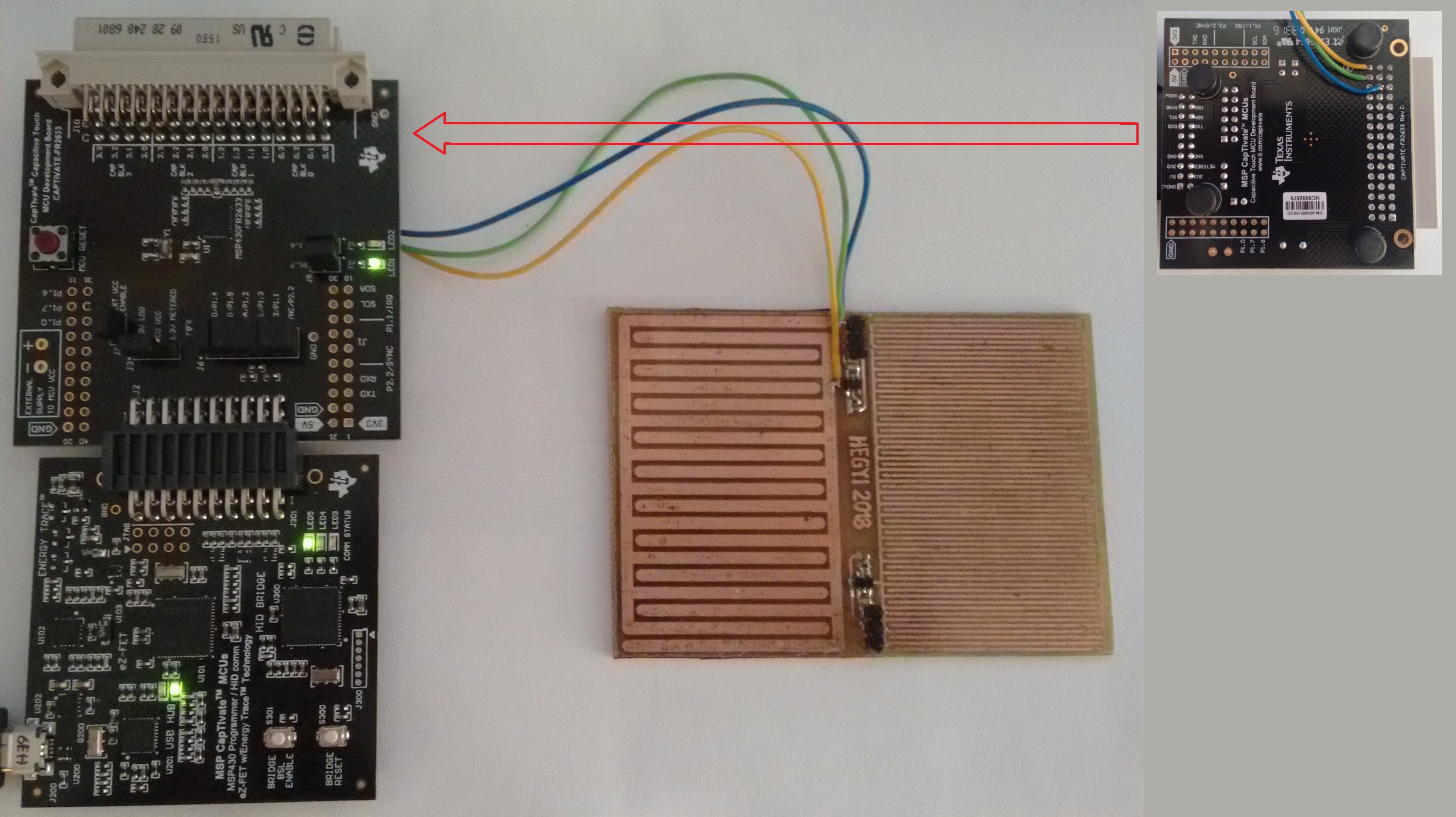
Noticed the MSP430FR2x family which has a really low power cap sense (<10-20uA) but CapTIVate chips seems to be for touch which rejects rain - can they be used as rain sensors with some reconfiguration?

Any idea is welcome,
TY

  • Hi TY,

    Interesting question. Are you trying to sense when there is moisture (rain) on the surface of something? If so, then yes, it is possible, depending on the amount of moisture you are attempting to detect. For example there is condensation, water spray and flowing water. Typically it is easiest to detect water when there is enough for individual drops to pool together. If there is significant amount of rain then this is not a problem.
    Tell me more about what you are attempting and I can steer you in the right direction.
  • I need to measure rain as accurate is possible with a non moving part low power solution.

    Probably it is not possible to measure in mm/inch but a Shower/Rain/Heavy rain/Storm would be enough if I could make it work. I have a solution which can count drops but it's not low power at all - would like to achieve the same in low power.

    The target is below 100uA - the CapTIVate sleep 3 modes are ~5uA but that will wake up in case of rain (if calibration for rain is possible) which might result in much higher power usages overall when is raining (MSP430FR2512 active mode is in the mA range).

    Ofc any other sensing solution idea is welcome if it is low power enough.
    I wanted to use a bucket sensor which sleeps till the bucket tips but the big funnel+bucket is not suitable for my case.

    Thank You,
    Brown

  • Ok, I understand.

    In this case, I don't think the CapTIvate solution is an option since you are trying to measure an accumulation of water rather than detect it on an object's surface. Although, with your idea of a bucket, CapTIvate could be used possibly as a liquid level detector, but you still have the issue of emptying the bucket and staying with your "non-moving" concept.
    And yes, the sleep current is rather small compared to the active current, which would be greater than your 100uA goal.

    Sorry to say but I can't think of any other solution that might meet your requirments.
    Perhaps someone else in the community can comment.
  • It would be fine to detect droplets on a capacitive surface as well - that would give a rough idea of the rainfall.

    Could that be achieved with CapTIvate?
  • It is possible, depending on the amount of moisture you are trying to detect and design of the electrodes.

    We have found that when operating CapTIvate in projected or mutual capacitive mode, as water droplets begin to accumulate over the electrode, a slight change in capacitance is detected. In this case the electrodes are copper traces designed into PCB with a 1-2mm plastic overlay (polycarbonate, glass, etc) covering the PCB to protect it from direct contact with the moisture. The water droplets cause a small change in the surface dielectric of the overlay making it slightly more conductive. As the droplets begin to coalesce over the electrode, the change in capacitance increases, but only up to a certain point, then no further change is detected. So this may/may not be useful.

    Second, using the same scenario above, but driving the electrode in self capacitive mode, it is possible to detect larger amounts of water accumulating or even flowing over the electrode because the water begins to "bridge" the e-field that is generated by the electrode to neighboring grounds on the PCB. This doesn't work very well with small water droplets however.

    So in theory, you could drive the electrodes both in projected and self cap modes to determine if moisture or larger amounts of water are present. It still won't tell you the exact volume or quantity of moisture.
  • Hi Ty,

    I have another thought.

    Disclaimer: The diagram, specifications and procedure are provided only for the purpose of this discussion, not a recommended design.

    If you want to experiment, you might try something as shown in the diagram below.

    This will give you an opportunity to test if this technology would be useful for your application and only requires some copper tape, a piece of glass or plastic, or any non-conductive flat rigid material that can tolerate exposure to moisture.

    If you don't already have a CapTIvate EVM, I would suggest using the CapTivate Touch Keypad BoosterPack with the MSP430 CapTIvate Programmer

    You can read more about the Touch Keypad Boosterpack here.

    Using glass or plastic sheet, I would apply the copper tape on the backside (don't let these get wet).  You will need to solder short wires to each.

    The wires would connect to GND and two of the prototyping pins located on the Touch Keypad Boosterpack.  Best if you can tape the wires down so they don't move around during the experiments.

    With the glass or plastic sheet tilted vertical or near vertical, try applying various sprays and flowing water.  I'll need to help you configure the software and get it up and running.

    Let me know.

  • We received yesterday the devboard - it is a MSP-CAPT-FR2633 - that was the one in stock at our supplier so it was "easy" choice :)

    As far as I see it does not have the boosterpack but it has three other sensor pads instead - is any of them better for rain tests than the other?

    We also need to figure out a way to measure power usage of the CapTIvate MCU separated from the rest - probably some hacking will be necessary.

    Brown

    Edit: just understood we need to make a new sort of a sensor board - that is doable, soldering is doable as well - we just need to know where to connect with the devboard instead of the boosterpack.

  • Ok, actually this is good news.  The MSP-CAPT-FR2633 is the full EVM, providing more flexibility and has boosterpack connectors on the MCU PCB. The MCU board also has a removable jumper specifically for measuring only the MCU current. You can read more about the MSP-CAPT-FR2633 EVM in the CapTivate User's Guide here.

    The MCU module has a large 48pin connector that can support up to 16 CapTIvate capacitive touch channels on the top row of pins.  The middle row is all grounded and the bottom row contains some digital signals. The connector supports the demonstration panels that come with the EVM, but there is no reason why you can't create your own PCB to connect to the MCU PCB.  If you just want to test an idea and don't want to go through the hassle of developing your own PCB, simply take wires from your electrodes and shove them into the 48pin connector on the MCU PCB.  If you want to go all the way and design your own PCB to the form factor you need with the MSP430FR2633 (or derivative) on your PCB, this is possible too.

    To understand the process of creating sensor project, refer to workshop link in the CapTIvate User's Guide.  The workshop shows you how to create your sensor(s) using the CapTIvate Design Center and tune your sensors. It won't show you how to create a PCB. It is assumed you already know how to do that.  It will also show you how to measure the MCU current using your EVM.  The really nice feature is the CapTIvate design center generates all the software to get you started with your sensor project.  The only code you would have to add is what you want the MCU to do when you detect the moisture.  This is done through a software "callback" and is also described in the CapTIvate Design Center documentation, Software chapter.

    You will have many more questions so don't hesitate to ask.  We'll help you along the way.

  • Hi Dennis, 

    We created our own sensor that looks something like this (there is copper tape at the bottom side - blue wire) :

    I successfully installed the Captivate Design Center, CCS and MSP430 compiler, and tested two of our available boards (phone board and BSWP) successfully. 

    Now I am looking to configure this home-made sensor board as a rain sensor, just as Brown above described. In the CDS I added a button with the following parameters: mutual, 1 element, then went to the MSP and configured it like this:

    I get pretty bad results and I'm wondering if i did everything right or not, if there are some major flaws in my setup please point them out. 

    Thank you for your valuable help,

    Istvan

  • See next post.

  • I am not sure what you're trying to point out by quoting that. Could you please elaborate?

    Thanks,
    Istvan
  • Hi Istvan,

    Ignore my previous response. Some type of cut paste error - not sure how that happened.

    Unlike self capacitive mode, in mutual mode you cannot directly expose the electrodes to a touch or mositure, as this effectively shorts across the RX and TX electrodes "killing" the e-field. You need to have some insulating overlay, such as plastic or glass, 0.5mm to 3mm thick, mounted on top of the the PCB and it should be held in place with an adhesive, such as 3M 467 or 468 double sided tape. The purpose is to prevent the overlay from shifting after the system is calibrated on power up and to prevent air from getting in between the PCB and the overlay.

    If you have already done this then what is the conversion_count and conversion_gain settings for your electrode? This can be seen in the sensor's properties window (double-click on sensor) in the conversion_control tab.
  • Hi Dennis,

    Yes, there is an insulating layer of scotch tape on the PCB surface, so there's no direct contact between the droplets/fingers and the copper traces.
    I have 500 entered to the "Conversion Count" parameter. The "Conversion Gain" isn't active, there is a "Frequency Divider" parameter instead, and it's set at f/4 (was left at default).

    Thanks!
    Istvan
  • I'm not sure why the conversion_gain is not active.  It should appear like the following.

    The conversion gain is typically set = 100 and for the electrode size you have, your conversion count can be probably 200 to 250 to start.

    Don't forget to click the "Apply" button!

    Then when you touch anywhere on the surface you should see something as shown below.

    The red bar indicates the "delta".  What do you get?

    You mentioned that you have copper tape on the backside of the PCB.  Does it cover the entire backside surface?

    Also, what are the two discrete devices in the photo and how are they connected to the electrodes?

  • Hi Dennis,

    This is what I am looking at:

    If I put my finger/spray water on the sensor, the readings are all over the place, I can barely catch a few red bar flashes. I couldn't get steady delta counts until now (only with the original devboard sensors).

    I have to go through all the settings, there might be something i checked/unchecked that got me to this slightly different user interface param set.

    The bottom of the PCB is covered with copper tape, and it's connected to the blue wire -> GND pad from the middle row of the harting connector.

    Thanks!

    Istvan

  • Side note: I'm pretty sure that the reason i don't see good reads is because of my configuration. I mean, the readings from the original capacitive touch panels and their respective source codes returned very good deltas.

    Istvan
  • I see - the problem is you are running the CapTIvate Design Center in 'basic' mode. You need to enable the 'advanced' mode.
    From the main menu in the design center select Options > Features> Advanced.

    Then set your conversion gain = 100 and conversion count starting with 250, and make sure you click the "Apply" button.
    You will have greater sensitivity and should see larger deltas. You will have to experiment with the conversion count to get suitable readings. Going above a conversion count of 1000 will start to add in some of the system noise so I wouldn't recommend going above that.

    Keep in mind that with the mutual configuration you will see the blue bar outline in the sensor's channel bar chart increase as you touch your electrode. It goes up because your finger is stealing charge away from the RX electrode as your body is grounded and it requires more conversions to fill the sampling capacitor. However, when mist or spray is applied, the water will begin to accumulate, bridging the RX and TX electrodes. Because the water has little coupling to ground (compared to your body when you touch the electrode) the water will help conduct the e-field between the RX and TX electrodes. Since water and the overlay have a dielectric greater than air (~1.0), to the electrode it appears only as though the overlay material becomes thicker and you will actually see the blue bar outline go down instead of up.

    As I described earlier in this thread you do need some mechanism for the moisture to couple to ground. In the drawing I posted, there is a strip of grounded copper tape which provides a path for the water to couple between the electrodes and ground.

    You can easily experiment with this by changing your sensor configuration to a self capacitive electrode, keeping the same RX pin as you have now. The TX pin will now become your ground by default. It's a simple change in the design center and update to your CCS project.

    Remember, the RX and TX mutual mode can be used to detect the small accumulation of moisture, up to a certain point.
    As more and more water accumulates and either pools or begins to flow, the water will need to couple to a nearby ground. Without the ground, the water is basically a floating layer added to the thickness of your overlay.
  • Hi Dennis,

    Spot on, I just got access to the other parameters. I will experiment and share my findings!

    Thank you!
    Istvan
  • Hi Dennis

    Long time we did not wrote here - the captivate design sort of works but the problem is what we suspected - if we set "wake up" to rain, a few hours of rain will drain our power source (keeping the MCU running full power).

    Is it possible to have the chip sleeping and doing measurements only 10% of the time? (100msec from every second for example).
    Or anything like that will mess up the deltacounts and calibrations?

    Sort of have the feeling we want to use this captivate design to do something for which was not built :)
    Is there any other low power TI capacitive solution suitabile for rain? Checked the automotive ones (FDC) but those are not low power at all, they don't need to be.

    Wondering if the solution with F2013 would not work better - we have this devboard too:
    http://www.ti.com/tool/MSP-EXP430FG4618
    The big difference here is that everything is tunable while at captivate lot of the code is running from ROM.

    regards,
    Brown

  • If you think about it, the technology is designed for HMI applications such as detecting when a button is momentarily pressed. This means 99% of the time the button is not pressed. When the button is pressed, it is only pressed for 1 sec or less. The MSP430FR2633 can put the CPU into sleep mode while the Captivate peripheral checks for the button "press". Only then does the CPU wake up.

    In your scenario, once it detects rain, it will continue to detect rain, just like if someone presses a button, but does not release it. And yes, this will keep the CPU in active mode and will drain a battery. You could set the "wake on prox mode" scan rate (which is the rate at which the Captivate peripheral scans the electrodes when the CPU is sleeping) to a very slow value. I believe maximum value is 2047 and translates into 2.047seconds when using the Captivate timer, but you could select the ACLK or VLO clock source to drive this timer even slower.

    There is another feature (or parameter) that can be set to cause the system to re-calibrate when a button has been pressed too long. It is called the "sensor timeout threshold" and is found in the sensor's tuning tab. I believe by default it is set to 65535 which effectively "disables" the feature. If you set this to say 1000, then after 1000 samples if the software still detects a button press, it will re-calibrate. Eventually when the button is released, this is detected as a "negative touch" and the system will immediately re-calibrate.

    In theory, for your application you could have the system re-calibrate after the rain is first detected and after so many samples it could re-calibrate with the rain on the sensors. When the rain stops the system should re-calibrate again. I have never tried this with moisture so I can't confirm this will work under all conditions.

    Yes, you can do self-capacitive measurements with many of the MSP430 microcontrollers that have the appropriate timer and comparator peripherals, but you will never achieve the same low power as with Captivate. And you will have to configure the software and library for your application and tune the response by hand. There is no design center.