Part Number: LDC1000-Q1
Hi everyone, I am using a LDC1000-Q1 in my application but I have some questions about the behavior of the chip. I have read more and more time the datasheet but nowhere is explained when the "Data Ready" flag is set to 1. The DS simply tells "no new data available" but what are the reasons that cause the data to be not available?
I have set all the registers and I am able to read data from the sensor, but from time to time this flag goes high and remains high for some seconds. I think, from what I have seen in some tests, that when you reach the maximum Rp output code (32768), this flag goes high, whereas if you reach the minimum Rp output code you haven't any notifications. But sometimes this flag goes high even if you have no target near the sensor and I'm reading good Rp data values.
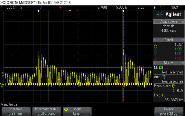
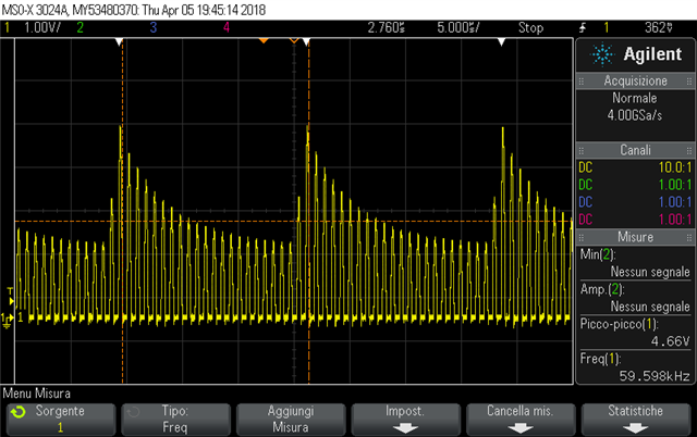
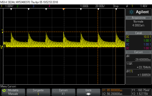
I have also noticed that the signal on the sensor has a strange behavior, like an amplitude modulation. No matter if I have set 1V/2V/4V as signal amplitude. Furthermore, what's the meaning of the amplitude value besides the real voltage value on the sensor? Why would I have to set 1V rather than 2V or 4V?
In the following images you can see the "amplitude modulation" that I mention before:
(Amplitude field in LDC configuration register set to 00:1V)
(Amplitude field in LDC configuration register set to 10:4V)
(same as before but zoomed out)
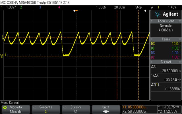
Also the signal on CFB pin has a strange behavior from time to time, like a "spike" that goes towards 0V
Any idea? Can you help me to avoid continuous "data not ready" flag?
Thanks in advance.
Fabrizio


