This thread has been locked.

If you have a related question, please click the "Ask a related question" button in the top right corner. The newly created question will be automatically linked to this question.

LDC1614: inductance value difference between low power sensor and high current sensor

Part Number: LDC1614

Hi...

My customer is testing LDC1614 through EVM with pattern coil pcb. they are checking the change of inductance value when finger is pressed on coil pcb.

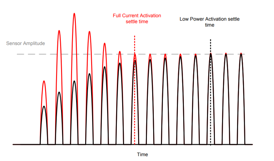
But there is inductance value's difference between "enable low power sensor activation mode"and "enable high current sensor drive".

Why is it so different like bellow pictures?

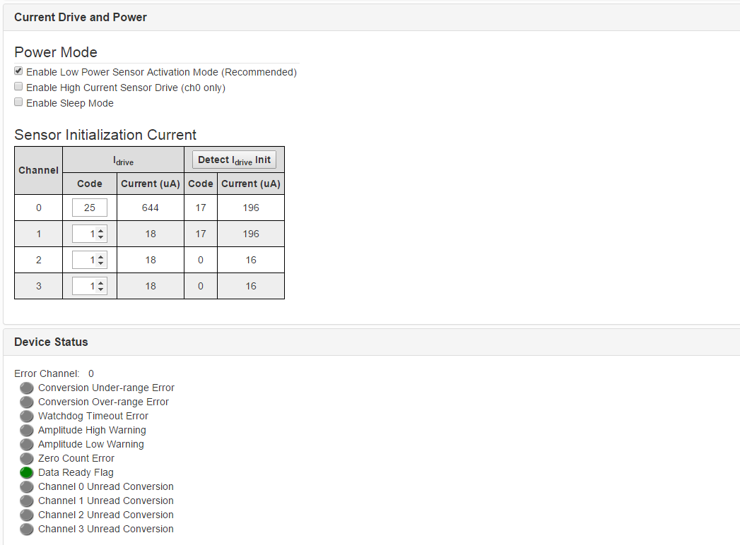
1. Low power sensor activation mode

    Inductance value is increased.
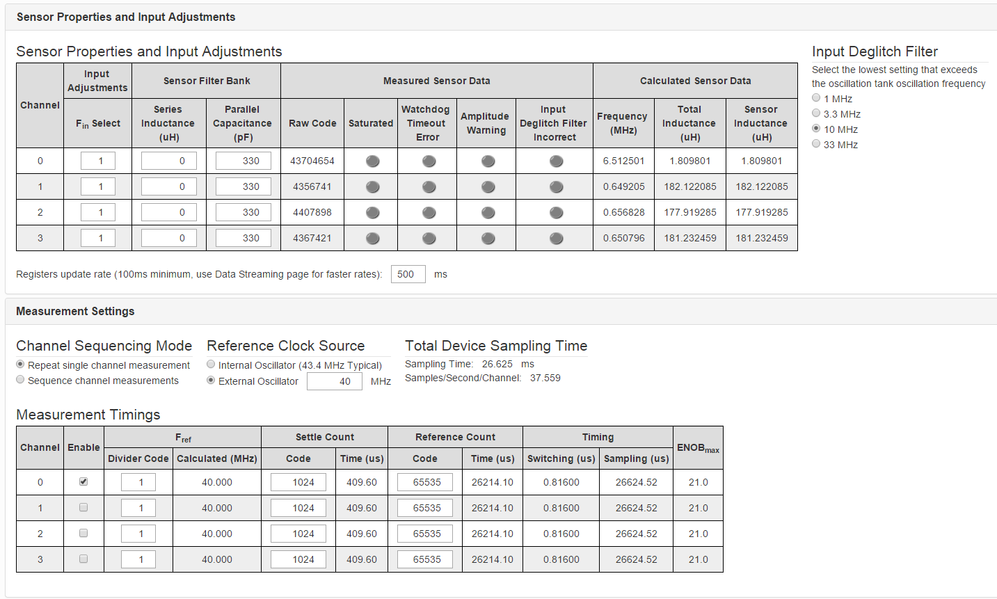
    

    Configuration


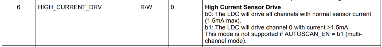
2. High current sensor drive

    Inductance value is decreased.


    Configuration


Regards

JP

  • Hello JP,
    I have a few questions that will help us better understand your issue.
    Is this a PCB coil? Or some other kind (wire-wound, etc)? When you press on the coil are you bending the traces? Is it wired to the EVM with short or long wires? What are the inductance and capacitance values for your sensor?
    Lastly, can you measure the IN0A/IN0B pins on an oscilloscope? It could be the case that you are over driving the coil with your current IDRIVE settings.
    Thanks!
    Luke
  • Hi Luke,

    Let me check your questions, and let you know that.
    Thanks for your reply.

    Regards
    JP
  • Hi Luke,

    The answers on your questions are as follows.

    Is this a PCB coil?

    -- Yes, it is a PCB coil.

    When you press on the coil are you bending the traces?

    -- No,  there is a metal material above a PCB coil.

    Is it wired to the EVM with short or long wires?

    --  Ch0 Wire 70mm + FPCB 30mm = Total 100mm

    --  Ch1 Wire 80mm + FPCB 90mm = Total 170mm

    --  Ch2 Wire 90mm + FPCB 90mm = Total 180mm

    --  Ch3 Wire 90mm + FPCB 40mm = Total 130mm

    What are the inductance and capacitance values for your sensor?

    -- Inductance is 2.1uH and capacitance is 1366pF.

    can you measure the IN0A/IN0B pins on an oscilloscope?

    Please let me know the solution.

    Regards

    JP

  • Hi JP,

    Thanks for the additional info! Something seems strange, which is that the sensor consists of L=2.1µH, C=1366pF, which should give a resonant frequency of 2.9MHz. However, your waveforms show a frequency of around 5.5MHz. This implies that the sensor is not operating at resonance. The reason may be the long wires you have attached between the sensor and device. Note that any wires between the sensor and device should be twisted to keep the parasitic inductance path small. You may also consider shielding the wires to avoid any stray capacitance pickup. You can also increase the sensor inductance from 2.1µH to something larger like 10µH to be the dominant source of inductance in the system. Lastly if you are operating at 5.5MHz, the maximum distance between the sensor and device should be <56mm to avoid transmission line effects like reflections and phase shifts from interfering with the resonant frequency. As a side-note, I see the oscillation amplitude is around 500mVpk or so. You should try to increase the amplitude to be between 1.2Vpk to 1.8Vpk to get the best noise performance. You can try increasing the IDRIVE setting to achieve this.

    Regards,

    Luke

  • Hi Luke,

    I'll check your comments at my side.
    I have additional some questions.
    The inductance value is increased at low power mode, but it is decreased at high current mode.
    Can you explain the reason why?

    When high current mode is enabled, ch0 is only activated.

    Can 4-ch(ch0~ch3) be activated at high current mode through S/W change or something?


    Regards
    JP

  • Hello JP,

    Just to clarify, there are two things that refer to high current mode. 

    The first is SENSOR_ACTIVATE_SEL which has a "Full Current Activation Mode" and a "Low Power Activation Mode"

    Setting this value low or high affects how the sensor initializes and this applies to all channels:

    Then there is HIGH_CURRENT_DRV which has "High Current Sensor Drive" mode. This only applies to channel 0 and it drives the sensor at the maximum drive strength (>1.5mA) regardless of the value programmed for IDRIVE.

    If you are referring to the first case with SENSOR_ACTIVATE_SEL and you are seeing differences in inductance value, then it is very likely that you have your SETTLECOUNTx value set too low. Try increasing this value and see if the behavior is more consistent. Refer to section 8.1.4.1 Settling Time of the LDC1614 datasheet for more information.

    If you are referring to the second case, then I would double check that your IDRIVE setting is set appropriately in normal power mode. Otherwise, it could be the case that High Current Sensor Drive is setting the current drive >1.5mA which could be over-driving the sensor such that the amplitude is >2Vpk which would activate the ESD circuitry of the device. This could make the sensor perform differently than expected.

    Regards,

    Luke LaPointe