This thread has been locked.

If you have a related question, please click the "Ask a related question" button in the top right corner. The newly created question will be automatically linked to this question.

LDC1000: Failure Proximity Code

Part Number: LDC1000

Hello guys,

I measured a wrong behavior of the proximity Code from the LDC1000. II used the LDC1000EVM with a ferrit coil with 80µH.

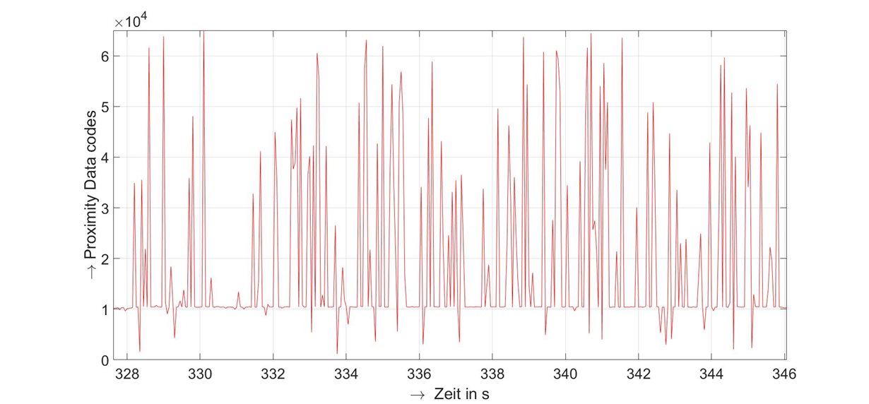
The Limit of the rp measurement is 32768 codes, but in some Distances I measured higher codes and the signal is very noisy.

This image shows the problem.

Can someone tell me why or how this faulty behavior comes about?

best wishes

André

  • Hi Andre,

    Could you clarify what test setup you are using? Are you using a ferrite bead as your sensor inductor? This will not work because it will not generate a magnetic field effective for LDC applications. Or are you using a ferrite core inductor instead of the PCB coil on the EVM? You also mentioned that at some target distances you see the noisy signal above. At what distances does this occur? Do you see this signal with no target present? Finally, it would be helpful to see a screenshot of your GUI settings.

    Regards,

  • Hello Kristin,

    thank you for your reply. I use a P Core Type Ferrit Coil on the LDC. The noisy Signal occur in a distance of 1,2mm. The Signal above or under this distance is clear.
    The Sensorfrequency is 1,2MHz and the voltage on the LDC Filter Capacitor is near 0,9Vpp.
    Can a voltage amplitude of the LDC Fitler capacitor be less than 1Vpp while it is not in saturation and is the same filtering effect achieved or is it attenuated?

    The settings:
    Rp_Min: 1796
    Rp_Max: 27704
    Proximty code from: ~230 to 25700
    minimum Sensorfreuquency: 185 ->B9
    Sensor Amplitude : 4Vpp
    Reference Frequency. 6MHz
    Response Time: 6144

    best regards,

    André
  • Hi Andre,

    Thank you for the additional information. The signal overall will be noisier as the voltage across the filter capacitor decreases, but it should be consistent across all target distances. You would not see such significant noise at only one target distance if this was causing your issue. 

    Could you provide oscilloscope screen captures when monitoring pins INA, INB, and CFB? It is possible that this issue is due to unstable oscillations at the 1.2mm target distance. 

    Regards,

  • Hi Kristin,

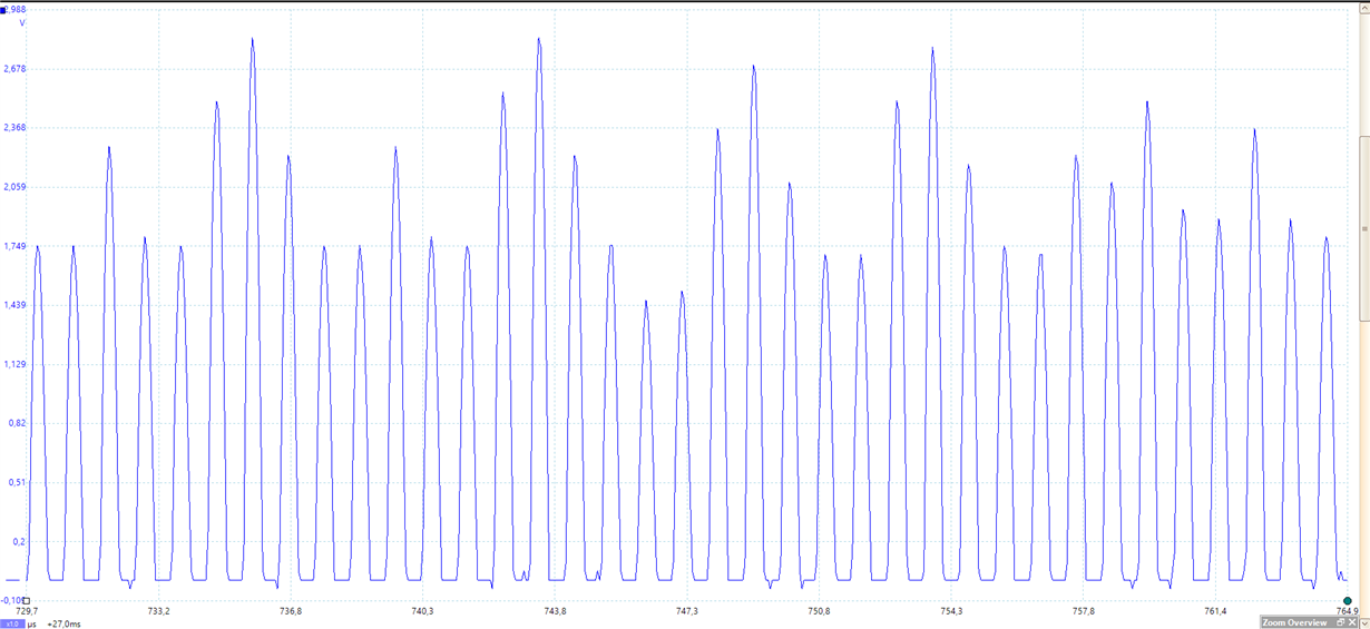
    the picture shows the oscillation at a faulty behavior. It is measured by INB to the ground.

    How should a good oscillation look at a small distance?

    Regards

    André

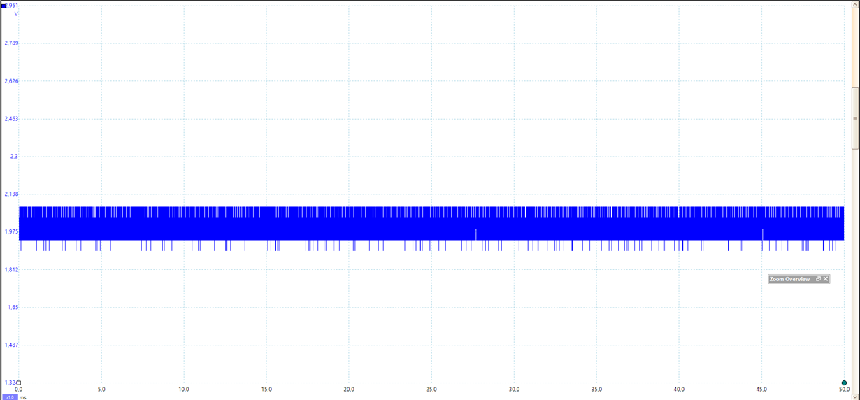
  • and that is the Signal on the CFB 

    regards

    André

  • Hi Andre,

    Thank you for sending your scope captures. The picture of the oscillations is very helpful, but the signal on CFB is zoomed out too far for us to use. Could you send a picture of the signal on CFB with the same time scale as the picture of the oscillations that you sent? I'll confer with my team about your issue and we'll have an answer for you on Monday.

    Regards,
  • Hi Andre,

    Could you measure the standard deviation of the output frequency (in codes) at several distance intervals? We suspect that at 1.2mm you will see a dramatic drop in the standard deviation. Using at least 30 data points per target distance and at least 5 target distances (including 1.2mm) should suffice. This can be measured fairly easily using the graph tools in the Sensing Solutions GUI. 

    We also noticed that the screen capture you sent us of the oscillation has sharp changes in the amplitude, which you should not see. The problems you are seeing are likely caused by the very small peak-to-peak voltage (about 200mV from your screen capture) at the CFB pin when your target is 1.2mm away. If this is causing the problem we suspect, the standard deviation test will confirm it. Figure 4 in this app note shows what normal oscillations should look like. Note that this image shows differential measurement, not single-ended measurement like the image you shared. 

    Regards,

  • Hello Kristin,

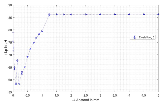
    thank you for your reply. I measured the standard deviation and I could not see a dramatic drop in the standard deviation.

    But the before the distance of the 1,2mm the frequency is constant and after 1,2mm I have a dramatic drop in the signal. The errorbars in this image discribe the 3*standard derivation

    regards

    Andre

  • Hi Andre,

    Thank you for the additional information. Unfortunately, the data you provided doesn't support our hypothesis, so we'll need to keep debugging with you. I apologize for the long process. It's a puzzling issue. 

    Could you provide more information about the physical construction of your coil? The diameter, the length, and the number of turns would be very helpful. Could you also verify that the voltage across the CFB capacitor is 1Vpp when the target is both less than and more than 1.2mm away from the sensor? Could you also get screen captures of the sensor oscillations at these points? We suspect that your issue is resulting from the reduced voltage across the CFB capacitor at the 1.2mm distance, but we would like to make sure that both the voltage across the CFB capacitor and the sensor oscillations are normal at other target distances. Finally, how did you measure the Rp of your coil, and what value did you find? We want to make sure the Rp settings are correct as well.

    Regards,

  • Hello Kristin,

    Sorry for the wait time, I was a bit too busy.

    The Coil has a diameter of 3,3mm and the turns are not known. I measurd th Rp with a LCR-Meter with an Amplitude of 1V. The Rs= 12,7Ohm and the Ls= 81,2µH this is a Rp of round about 29500Ohm at a frequency of 1,2MHz.

    For the Measurements I need some time.

    regards

    André