This thread has been locked.

If you have a related question, please click the "Ask a related question" button in the top right corner. The newly created question will be automatically linked to this question.

LDC1614: I bought ldc1614, and found some problems during the use

Part Number: LDC1614

Hi Dear engineers, I bought the ldc1614, and found some problems during the use. If I can answer for me, I will be very grateful.

Question 1: Why does the LED on my ldc1614 turn red but the display is connected. There is normal data reading, this phenomenon probably happens after I remove the original coil

Question 2; the problem with the new version of gui. First of all, the new version of the gui you do not seem to have some guidance video, and secondly, under the win10 system is not only the new version of the gui.

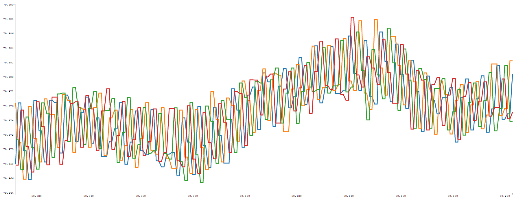
                  Most importantly, during the use, I found that it has spikes. Why does the inductance value displayed on the gui interface have spikes?

Question 3: After reading the register, I found that the last three bits of the register have been unstable. What is the reason?And what should I do to eliminate this effect?

Question 4. Only these frequencies can be chosen, why can't I input the resonant frequency like the ldc1000.

Finally, I want to know what the setting interface is on the gui. How to set it up to better adapt to the new inductor.。

Thanks!

  • Hi,

    Q1) The LEDs follow the following pattern after the device is plugged in and powered on:

    1. The Red LED turns on to show that configuration has begun.
    2. Both Green and Red LEDs turn on to show the EVM is ready.
    3. If the GUI is streaming data, both LEDs will turn off to show data is being read. The Green LED will turn on to show the cycle has been
    completed.
    4. If the EVM is no longer connected, the Green LED will turn off and the Red LED will turn on.
    5. If something is wrong with the I2C communication, the Red LED will blink every 100 milliseconds.

    Q2) While we do not have a video for the Sensing Solutions GUI, we do detail how to use it in the LDC1614EVM User's Guide.
    Could you provide the units of your graph so we can learn more about the spikes you are seeing?

    Q3) Which register are you referring to? One of the data registers?

    Q4) The device will determine the appropriate resonant frequency of the LC tank and drive it with this value, so there is no need to input a resonant frequency.

    Q5) The LDC1614EVM User's Guide will be the most helpful for customizing your GUI settings.

    Regards,
  • Full image of the spike

    The coil is 16uH and the capacitance is 560pF. I want it to be in the best condition. Now the inductor is placed under no-load conditions, that is, there are no metal objects around.

    The LED display is as shown above. Is this normal? I didn't find it flashing. If it is not normal, how can I set it?

    In addition, can the new GUI interface use two ldc1614 at the same time?

    Thank you for your answer!

  • Hi,

    If you are able to stream data with the GUI, I wouldn't worry about the status LED.

    If there are no metal objects near your sensor, the spikes could be caused by changes in capacitance. Can you describe your testing environment, as well as the type of capacitor you are using? In addition, are you using a PCB coil inductor or another type of inductor?

    Finally, it's not possible to use more than one LDC device with the new GUI.

    Regards,
  • I am sorry to reply you until now,and I have been adjusting these days,I have been adjusting these days and got a good waveform. The previous spike should be a problem with the setup. I added a shield to the wire and got a very good waveform. I am using a wound chip inductor, and the capacitor used is a normal chip capacitor.Here are some of my newly discovered issues.

    1、My inductance value is 47uh, but it is only close to this value when the external clock reference is 40mhz, and it is greater than this value.

    2、I want to increase the current through the inductor. I don't know how to increase it. I chose the settings as shown below, and then the data flow becomes like this. Can you provide suggestions for increasing the current or voltage?

    In addition,I am using four probes to work at the same time.

    thanks!

  • Hi ,

    I'm glad to hear that shielding your cables solved your spikes issue.

    1. The GUI's inductance measurement is actually calculated from the raw code value of the EVM, which is a ratio of the sensor frequency to the reference frequency. This means that both changes to capacitance and inductance can change the sensor frequency, which will influence the GUI's calculated inductance value. We generally recommend using C0G grade capacitors because they have very low thermal drift. In addition, any parasitic capacitances will change the inductance value from the real value. The measured frequency will be very accurate, but it will not exclusively represent the LC component values.

    2. If you are unable to change the sensor current using the table in the configuration page, try changing the value in the register page as well. You can monitor the voltage of either INxA or INxB with an oscilloscope. If it changes, you've successfully changed the sensor current.

    Regards,