This thread has been locked.

If you have a related question, please click the "Ask a related question" button in the top right corner. The newly created question will be automatically linked to this question.

IWR1443: IQ data question of IWR1443

Part Number: IWR1443
Other Parts Discussed in Thread: AWR1642,

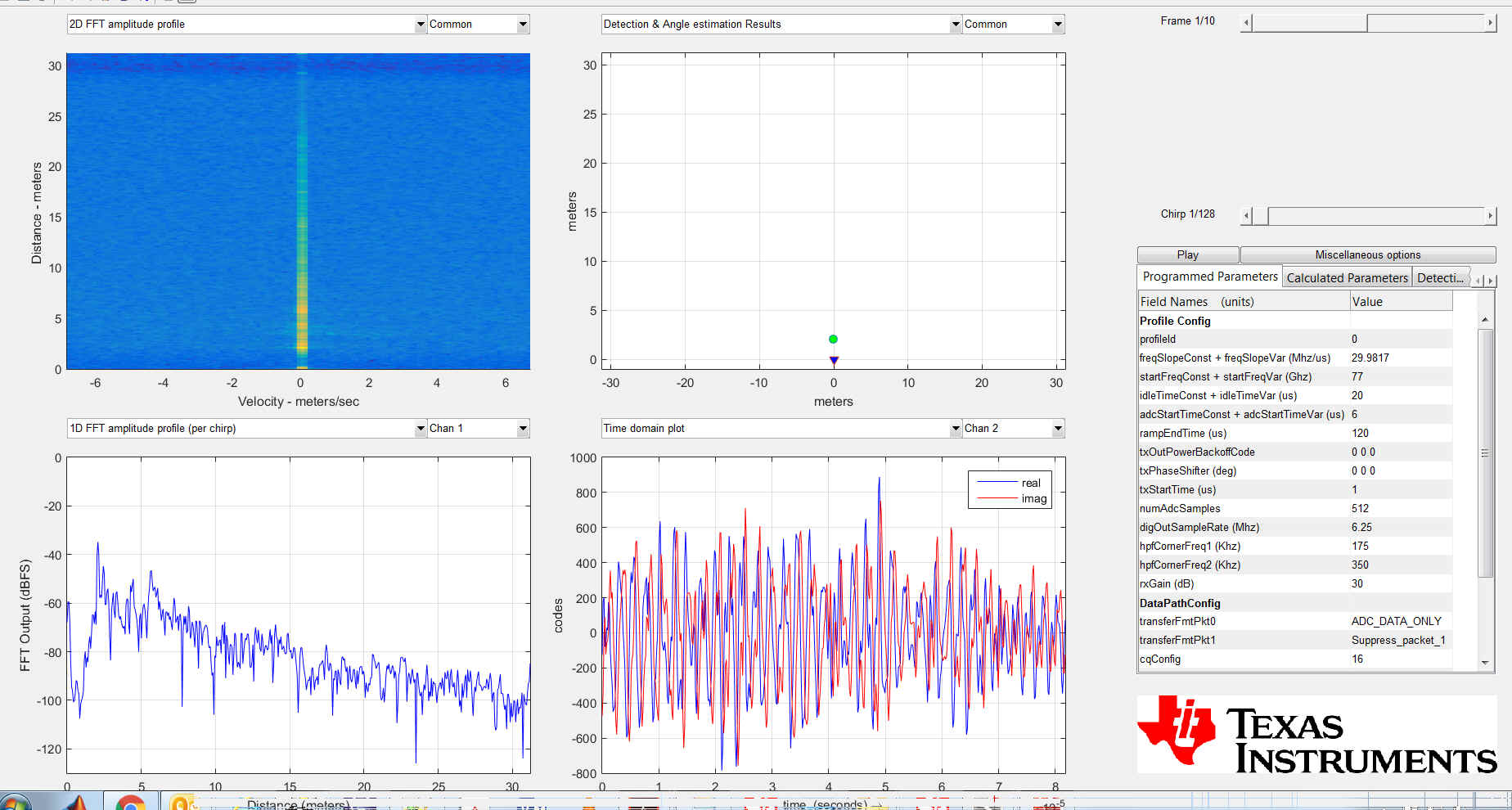
1. ADC I/Q data are saturated with minimum receive Gain 24, any other way to reduce the gain?

2. in receive subsystem page 50 of IWR1443 data sheet, what "saturation detection do"?

3. Can ADC data be averaged before sending to FFT accelerator?

Can anyone answer these questions?

Thanks,

  • Hi Feng, can you provide more detail for questions 1 and 2?

    thanks, dave
  •  Hello Feng,

    If this is on your-own hardware it may be possible.   Normally the patch antenna has 8-9db gain, there are losses reflecting off the target.   The Rx LNA has 24-48db gain.   If you think this is based on your Tx reflecting off a target, you can use the Tx backoff in the ProfileCfg, try to backoff by 10 to 20 db (1db per count).  

    I have not seen this on the EVM.

    Answers Q1 - this is not normal.   I  would use the mmWave Estimator and Radar Studio and reenter your chirp / system parameters.

    With the EVM, and a Corner Reflector .5m equivalent at 8-10 meters, with 30-36db gain, on the EVM I do not get saturation.   I have attached a picture.

    Answer Q2 - in the production version (ie ES3) for the ASILB version of the AWR radar devices, there is RF monitoring, included that the BSS processor can look at specific RF or digital points, and report errors if the signal level is too high, too low, or detects interference.  This information is not yet available from the designers.   There is a description of Built in tests for the AWR1642.

    Answer Q3 - the ADC buffer can be processed differently through Hardware Accelerator (HWA) Programming, which is customized by the user.  There is a digital filter capability,  You could create a scaling factor with the filter coefficients (use an impulse tap and vary the value).  

    I think you should look at the mmWaveSDK capture demo, and capture the raw ADC Buffer data.   while the internal data path goes from 12bits, to 18bits throughout the DFE, you can round the output to 12,14, or 16bits.   When you capture the signed complex, or signed real data, you can look at the signal levels at the DFE output.  

    You can route the data directly to L3 memory, without HWA processing to make sure its not an HWA concern.

  • The Range plot in the picture is complex magnitude. The point around 160k yaxis is the Corner reflector target.
    Regards,
    Joe Quintal
  • Hi Joe,

    Thanks for the response, the plot that you posted from mmWave Visualizer is the frequency domain data, I am talking about the time domain I, Q data that you can capture the data from L3, I use IWR1443boost to capture the I/Q data with a six inch corner cube at around 1.5 meters and 3.5 meters, all the I/Q data (time domain ADC data) are saturated with the receive Gain 24 which is the minimum gain that I can set. you talk about the transmitter back off, do you mean the transmitter gain is adjustable? I do not see this feature from the IWR1443 data sheet, do you know the transmitter adjustable gain range (or the back off gain range)? how do you paste the picture in this Forum, why it not allow me to do this?

    Thanks,

  • DataIQ.docxThe saturated I/Q data that I captured through Capture Demo

  • Hi Joe,
    What does the Tx back off do? It seems only allow Tx back off 24, I tried 25 I get config error, does 24 means 24 dB gain back off or something else? the I, Q (ADC) time domain data are still saturated with receive gain 24, Tx back off 22.
  • Who can answer my question?

  • Hello,

    To paste a picture, you need to select Use rich formatting.  Then paste a JPG from file, or paste from Word (put your picture in a word file, then copy and paste.

    I don't have a corner reflector that is 6" per side, our Lab has a 4.25" per side.   I will have to setup a capture demo, to send you the data.   There is also another tool, called Radar Studio, but to use this you need the DevPack board, and a TSW1400.  It captures the LVDS output from the 1443, 1642 devices.   I will try to post a lab result Monday.

    The transmitter backoff is a standard mmWave parameter.  Please look at the mmWave SDK User Guide.   It is in the ProfileCfg.   You can save your mmWave Visualizer experiment to a .cfg file, change the Tx backoff parameter to 10 (its currently 0), that should result in 10db less transmit power.

    In my case, with a 4.25" triangle reflector, at 2.1meters, RxGain 30, Tx backoff, along bore site of Tx antenna, my IQ count is < 1000.   

    I have included a screen shot from Radar Studio.   We will have to replicate this with mmWave data capture, I will work on that. (probably Monday).

    Regards,

    Joe Quintal

  • Hello Feng,

    Can you provide the profile configuration you used?

    Also, can you provide the .dat file you used to plot the data?

    Lastly, to make sure you are analyzing the data properly, can you try plotting using the provided 'capture_demo.m' matlab file located at C:\ti\mmwave_sdk_01_00_00_05\packages\ti\demo\xwr14xx\capture\gui?


    Regards,

    Adrian

  • Here is the configuration and the dataDataCFG2DemoRx24back22.dat

    flushCfg
    dfeDataOutputMode 1
    channelCfg 1 1 0
    adcCfg 2 1
    adcbufCfg 0 0 1 1
    lowPower 0 0
    profileCfg 0 77 16 7 139.33 22 0 28.58176 1 985 7500 0 0 24
    chirpCfg 0 0 0 0 0 0 0 1
    chirpCfg 0 0 0 0 0 0 0 1
    frameCfg 0 0 2 1 20 1 0
    setHSI CSI
    sensorStart

  • 1. The rich formatting is what I always use, I paste the picture to the word and copy the picture from the word to Forum, the forum only allow to paste the text from the word, not the picture.
    2. you do not answer the transmitter back off range, and if the back off means to reduce the transmitter gain? I do not find these information from mmWave user guide.
    3. you can use any wall as target, such as ceiling and the wall of the cabinet .

    regards,
  • Hello Feng,

    Regarding the Saturated ADC data question.
    Based on the dat file provided the data seems to be range of +/-100 numerical range so it doesn't seem to be saturated.

    Please make sure you are converting the data to decimal equivalent as the collected data is in 2's complement form.
    There is an m file in the "Capture" Demo which is part of mmWave SDK.
    It converts the data before plotting it.

    After setting the chirp size/number of samples based on your config it should allow you to plot the collected data.
    This is mentioned in the SDK user's guide under Capture demo section for IWR14xx.

    Hope that helps.
    If you are not able get through the plotting step, then please let us know.

    Thank you,
    Vaibhav
  • Hi Vaihav,

    I am confused by you explanation about "Collected data in 2's complement format", The saved data is 16 hex format, which is the data that I put on the forum, it is not binary. here are some of the data and its converting, how do you convert 16 hex "FFCC" to less than +/- 100? if you look at the signal data like FFCC (65484 decimal equivalent), FFF4 (665524), FFD8(65496), FFDD(65501), FFF4 (65524), this kind of data tell me the signal are saturated with the closed amplitude in continuous 6 bins. Is this the data you look at? I am also believe the signal will be saturated since I measured the distance around 2 meters and 31meters, with the same gain settings, according to the space loss if you get the signal amplitude +/-100, what you get at 31 meters?

    001A 26
    FFD0 65488
    0017 23
    FFCC 65484
    FFF4 65524
    FFD8 65496
    FFDD 65501
    FFF4 65524
    FFC8 65480

    regards,

  • Feng, these are 16-bit SIGNED ints. FFCC = -52.
  • In mmWave_sdk_user_guide page 14, it says the data format is 16 bit hex TI style. Can you take look at this?

  • "TI style" simply means there is no 0x prefix. It has no bearing on whether the values are signed or unsigned - they can be either depending on the application and it is up to you to know what they are. The mmWave documentation states that these are signed as you would expect ADC I/Q data to be.
  • Thanks David!