This thread has been locked.

If you have a related question, please click the "Ask a related question" button in the top right corner. The newly created question will be automatically linked to this question.

AWR1642BOOST: CAN bus bit 0 error

Part Number: AWR1642BOOST
Other Parts Discussed in Thread: MMWAVE-SDK, AWR1642

Hi,

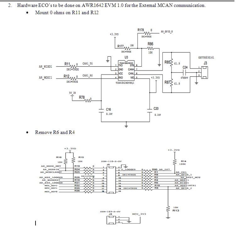
I'm trying the CAN FD example on AWR1642BOOST board, but it is always reporting bit 0 error.

I've tried following

- checked the CAN pins in multimeter as well as in DSO, the CAN bus always stays recessive.

- changed the CAN FD configuration to "CANFD_MCANFrameType     frameType = CANFD_MCANFrameType_CLASSIC;"

- made the STB pin of CAN transceiver which is connected to GPIO_0 as low.

- tried with two boards connected to the same CAN bus

Only the loopback examples are working. EVM-EVM and RX/TX examples are reporting the bit 0 error.

Thanks and regards,

Chidvilas

  • Hello Chidvilas,

    We have not seen this error reported by you in our testing of the CAN/CANFD interface.

    Do you have a PCAN/Canoe analyzer connected on the same bus?

    -Raghu
  • Hello, Raghu,

    I've tested with microchip CAN analyzer also. In rolling trace mode, no messages were seen.

    - Chidvilas
  • Below is the snapshot of the  Classic CAN messages and the CANFD packets without any error in the PCAN application using the MMWAVE-SDK code with just the frametype changes.

    I am not familiar with the microchip CAN analyzer , but I am expecting it to have a settings for the timing parameters . The SDK example is working at 1MBits/s Nominal bitrate with sample point of around 75%. 

    Below are the setting we have in the PCAN for the timing parameters

    Have you done similar settings in your microchip CAN analyser?

    -Raghu

  • I've set the Bitrate to 1MBits/s.
    There are no timing settings in the CAN analyzer that I'm using.

    One more doubt, what is the behavior of CAN node if it is not connected to the BUS. I think it should report acknowledging errors and not the bit 0 errors. But here, if I keep the node(AWR1642BOOST) open and run the
    "4. MCAN External Tx/Rx test",
    then I'm getting
    "Debug: LEC : 5"
    From the TRM, '5' is bit 0 error. This same error is coming even if the node is connected to the bus.

    Please, if possible, run the CAN-FD example without connecting the node to the bus and see the error.
    - Chidvilas
  • Chidvilas,
    Can you confirm if you have done the required ECOs to the AWR1642BOOST for the CAN interface to work?

    -Raghu
  • I haven't changed any hardware jumper configurations. What do ECOs mean?
    In the user guide, www.ti.com/.../swru508a.pdf, from section 2.3.3, it is mentioned that R11 and R12 have to be made 0 ohms. But from the schematics they are already made to 0 ohms.

    Are there any hardware configurations that has to be changed? If so, point me to them.

    FYI, for CAN connections I've connected the BUS to J3 of the board.

    - Chidvilas
  • Chidvilas,

    You will need to do the below modifications on the AWR1642BOOST for the CAN to be functional. 

    By default, the AWR1642BOOST do not have these changes. Please do the modification and you should be able to see the CAN data on the CAN Analyser.

    -Raghu


  • Hi, Raghu,

    This has solved the issue with the transmission error. Now the error status has been changed to '3' - No ack. Is it safe to assume that AWR1642 is transmitting properly?
    I've connected classic CAN (not CAN FD) node on the bus, but this node is not receiving the messages.

    Is it possible to run classic CAN example given in the mmwave SDK or does it need any hardware modifications?
    Thanks,
    Chidvilas
  • Chidvilas,

    The CAN example given in the MMWAVE-SDK is for the CAN(DCAN IP) interface on the AWR1642.    For the DCAN to work on the AWR1642, you will need to perform the below ECO's to the DEVPACK

    DCAN ECO on the Dev Pack:

    1)      Remove R16 & R43

    2)      Mount 0 ohms on R17 & R39

    The CAN-FD example is for the CAN-FD(MCAN IP) interface on the AWR1642 . The CAN-FD application can work to send/receive classic CAN messages(8 bytes) if the frametype set to  "CANFD_MCANFrameType_CLASSIC" which you are already doing. The ECO's required for this to work was given in my previous post , which you have confirmed to be working.

    I am not able to understand why you are getting these errors. 

    Can you please send me the pic of your setup with the CAN /CANFD connections and how they are connected to the BUS ? 

    Thanks,

    Raghu

  • Raghu,

    This is how the boards are connected. I'm running the same code on both of the boards through two CCS instances. I'm running "mcanEVM_EVMtest" with one of the boards transmitting and the other board receiving.

    Note: I've added this line of code "scanf("%d", &MCANMode);" before "if (MCANMode == MCAN_APP_TEST_EVM_MODE_TX)" for selecting transmitting and receiving mode.

    I've started the reception before transmission so that the receiver would be waiting for the message. Transmitter is stuck at the line "while (gTxDoneFlag == 0);" and similarly the receiver is stuck at "while (gRxDoneFlag == 0);". 

    If I run the "mcanTransmitTest", it is reporting LEC as 3.

    Thanks,

    Chidvilas

  • I do not see any issue with EVM-EVM testing. I checked it on 2 EVM with one of the EVM transmitting and other receiving to messages. I am not using scanf() to give the input, instead have image downloaded to Transmit EVM with "MCANMode : 1" and the receive EVM with "MCANMode:2". 

    Below is the logs from the CCS console for 100 messages transmitted from TX EVM and received  on the RX EVM .

    Transmit side:

    Debug: Message Identifier : 197

    Debug: Direction : Transmit
    Debug: Number of interrupts received : 100
    Debug: Number of messages processed : 100

    Feature: EVM to EVM testing: Passed

    Receiver Side:

    Debug: Message Identifier : 197
    Debug: Direction : Receive
    Debug: Number of interrupts received : 100
    Debug: Number of messages processed : 100


    Debug: Receive passive status : 0
    Debug: Transmit Error Counter : 0
    Debug: Receive Error Counter : 0
    Debug: Error Logging Counter : 0


    Debug: LEC : 7
    Debug: Activity : 1
    Debug: Error Passive : 0
    Debug: Warning Status : 0
    Debug: Bus Off Status : 0
    Debug: Data Phase LEC : 7
    Debug: Rx ESI flag : 0
    Debug: Rx BRS flag : 0
    Debug: Rx CAN FD : 0
    Debug: Protocol Exception Event : 0
    Debug: TDC value : 0

    Feature: EVM to EVM testing: Passed

    You can remove the scanf() and try to load different images in the device and try the EVM-EVM setup.

    Thanks,

    Raghu

    ---------------------------------------------------------------------------------------------------------

    Please click the Verify Answer button on this post if it answers your question.

    ----------------------------------------------------------------------------------------------------------

  • xwr16xx_canfd_mss_evm.zip

    Hi, Raghu,

    I've removed the scanf lines and compiled them by hardcoding "testSelection" and "MCANMode" for transmitting and receiving separately. These are the binaries I've tried. Would you please test them in your boards. So that I can confirm that my hardware is working fine. BTW, my mmwave SDK is mmwave_sdk_01_00_00_05.

    Thanks,

    Chidvilas

  • Chidvilas,

    I believe you already confirmed your setup to be working by testing the CAN external test and checked the CAN messages on your CAN analyser.

    I have attached the binaries that we have tested on the EVMs. Please check them.

    xwr16xx_Can_Evm-Evm.zip

    Thanks,

    Raghu

  • Raghu,

    External testing is also not working. I've tried your binaries and the issue is same. Would you please give me your contact info, so that I can contact you directly.

    Thanks,
    Chidvilas
  • Chidvilas,

    I guess the ECO's are incomplete.
    Have you done mounting of 2 resistors and unmounting of 2 resistors on the AWR1642BOOST?

    If the ECO's are done then you should have the external TX/RX working just fine .

    -Raghu
  • Raghu,

    ECOs we have made:
    1. Connected R11 and R12 at the respective places with 0ohms.
    2. We haven't removed the resistors R4 and R6 because those are connected to open pins i.e. J5 connector and we are not connecting anything to J5.

    By making these changes, our error (LEC error) has been changed from '5'(Bit 0 Error) to '3' (Ack Error).


    We have tested with your binaries also. It seems that you're having a different version of the code from ours because when debugging, the debugger is pointing many lines ahead.

    It is not working in both the CAN modes, by configuring "fdmode" in "CANFD_MCANInitParams" structure either as 1 or 0 and also changing frametype accordingly.

    We have tried EVM_EVM test by connecting CAN TX (before CAN transceiver)of one board to CAN RX of other board and shorting the ground of both. Still, the issue is same.

    From the CRO probe, we were able to see some signals from CAN TX and from CAN RX, but we're not sure whether the data is proper or not.

    Would you please share register dump from your setup before and after calling the function "MCAN_txBufAddReq" in "canfd.c" for TX and RX.

    Please, if possible test our binaries on your boards.

    Thanks,
    Chidvilas
  • Chidvilas,
    The CAN and SPI lines are muxed .

    You will need to remove the R4 and R6 for your CAN lines to work.
    Please do the modifications as mentioned for the CAN to be functional.

    -Raghu
  • Raghu,

    We got the resistors R4 and R6 unmounted. There is no change in the behavior of operation. Still, the errors are same and it is getting stuck for transmission and reception to complete.

    Are there any ECOs for STB pin of CAN transceiver? Now it is connected to ground through 10K.

    Would you please provide us with the register dumps of MCAN configurations, MCAN buffers, and pinmux configurations. 

    Thanks,

    Chidvilas

  • Thanks Raghu, this resolved the issue.