This thread has been locked.

If you have a related question, please click the "Ask a related question" button in the top right corner. The newly created question will be automatically linked to this question.

AWR1443BOOST: How to increase the detected point for 3D point cloud visualization

Part Number: AWR1443BOOST

Hello,

We are currently using the AWR1443BOOST to detect the electric lines in our project. The problem is that there are too few points detected by the radar so we can't get a viable point cloud visualization. We tried the mmwave visualization ROS driver as well, and we can see the object moving but the shape is barely understandable.

Is there any way that we can increase the number of points or create a good point cloud visualization? If someone knows please give us some guidance and direction.

Thank you very much.

  • Hello Cuong Pham,

    The query on the number of objects detected and details of the detection matrix is answered below:
    e2e.ti.com/.../2306304

    Thanks,
    Raghu
  • Hi Cuong Pham,

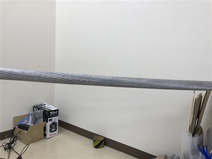
    Are you interested in seeing the wires as lines in the plot? Could you share the current picture? What is the material the wire is made of? Is it metal? Is it smooth?

    In general, if the wire is stationary, no more than a single detected point would be seen. Howver, if the wire is in motion, and is made of metal, and rough, I'd expect to see more detections.

    Regards
    ANil
  • Thanks a lot Raghu. We've already checked that out but it seems that increasing MMW_MAX_OBJ_OUT only works for 2D plotting. Is there anyway to increase the maximum object point with elevation, and if there is such a way, is it harmful to the radar or something like that?
  • Hello Anil,

    Thank you very much for the answer. Yes we want a way to visualize the wire in the scene. This is the point cloud visualization, and it's really difficult to "understand" which one is the wire.

    The wire is covered multiple metal lines, the pattern is repititive (Bragg pattern). You can see it in the below picture. The electric line is stationary but the radar will be carried and moved with the drone so basically there will be movement between the electric line and the radar.

    We also think about getting raw signal from the radar and process to get the angle of the object corresponding to the shape of the electric line cover pattern. Is there anyway to do such a thing?

    Thank you very much.

  • Hi Cuong. 

    One of the difficulties with radar is that it's angular resolution is dependent on the number of antennas. For e.g., the 1443 has 4 Rx, and 3 tx, antennas. Of these only 12 are used for azimuth, meaning that the azimuth angle resolution is limited to ~15 degrees. What this means is that if there are two reflectors at the same range, and same velocity (as they should be in the case of your test), radar would have trouble distingushing them.

    Fortunately, there may be a solution. Radar has excellent range and velocity resolution. Could you mount the radar on your drone, and repeat the experiment? 

    Since the drone is moving w.r.t to the wire, the parts of the wire would be resolved in velocity and range. It is possible then for the shape of the wire to become apparent. If you don't have an active drone, could you try placing the radar on a moving platform and simulating the experiment. 

    Regards

    Anil 

  • Hello Anil,

    We understand that it is possible to mount the radar on a moving platform and register the points using odometry data. We are currently trying it too. Anyway that is not the exact purpose of our project. We aim to use radar and a more simple solution to detect the power lines and the drone will automatically recognize the path and move along the power lines (as long as there is the sign of power lines).

    Is there any way that we can limit the radar scan range to a specific range (such as from 2 meters to 10 meters), and some how make the radar to detect multiple points on the object? If that's possible, could you please provide us with a straigh-forward direction, such as where in the codes that we can modify?

    Thank you very much. Our project is currently stuck at this point. As long as there are feasible input of the lines, the recognition is not a problem because there are many algorithm that can recognize the line feature.

    Best regards,

    Cuong

  • Hello Cuong,

    Regarding your question on limiting the range of detection, you can use the peakGrouping API (pg 25 of the mmwave SDK userguide). Note that the 5th and 6th inputs allow you specify the min Range and the maxRange (in Range indices). Also, disable peakGrouping in both doppler and range.

    You can then reduce the thresholds in the Cfar API (for both range and doppler) to see more detected points.

    If possible, could you share the chirp configuration that you are using? In any case, make sure that you've configured for the best range-resolution (i.e. the highest RF-bandwidth).

    Regards
    Anil
  • Dear Anil,

    Currently we've been getting back to our radar project. In our understanding, the range resolution is the distance between each range index, such as for the range resolution of 0.04 (m), the range index 0 will be 0 -> 0.04, index 1 will be 0.04 -> 0.08, index 2 will be 0.08 -> 0.12, and so on. So we tried to limit the detection of objects between a minimum and maximum range, by modifying, for example, the 5th input (minRangeIndex) to 100 and the 6th input (maxRangeIndex) to 200 in order to detect objects between 100 * 0.04 -> 200 * 0.04. However, the result is that the radar can still detect the objects which are closer than the minimum range. Could you please tell us what is not correct here?

    This is one of the configurations that we tried:

    % ***************************************************************
    % Created for SDK ver:01.00
    % Created using Visualizer ver:1.1.0.1
    % Frequency:77
    % Platform:xWR14xx
    % Scene Classifier:best_range_res
    % Azimuth Resolution(deg):15 + Elevation
    % Range Resolution(m):0.044
    % Maximum unambiguous Range(m):9.01
    % Maximum Radial Velocity(m/s):1
    % Radial velocity resolution(m/s):0.13
    % Frame Duration(msec):100
    % Range Detection Threshold (dB):15
    % Range Peak Grouping:disabled
    % Doppler Peak Grouping:disabled
    % Static clutter removal:disabled
    % ***************************************************************
    sensorStop
    flushCfg
    dfeDataOutputMode 1
    channelCfg 15 7 0
    adcCfg 2 1
    adcbufCfg 0 1 0 1
    profileCfg 0 77 267 7 57.14 0 0 70 1 240 4884 0 0 30
    chirpCfg 0 0 0 0 0 0 0 1
    chirpCfg 1 1 0 0 0 0 0 4
    chirpCfg 2 2 0 0 0 0 0 2
    frameCfg 0 2 16 0 100 1 0
    guiMonitor 1 1 0 0 0 1
    cfarCfg 0 2 8 4 3 0 1280
    peakGrouping 1 0 0 45 113
    multiObjBeamForming 1 0.5
    calibDcRangeSig 0 -5 8 256
    sensorStart

    Thank you very much for the support!

    Cuong

  • Hi Cuong,

    Your understanding of the range resolution is correct.
    As per your script the minimum start index is 45 and the maximum is 113. So the nearest object would be about 20m and the farthest object detected would be at 50m. Was that your intention?

    Regards
    Anil
  • Dear Anil,

    If the range resolution is 0.044 (meter), isn't it should be minimum = 45 * 0.044 = 1.98 (meter) and maximum = 113 * 0.044 = 4.972 (meter)? So it means nearest object will be from around 2 meters to 5 meters, but why multiply it by 10 so it'd be 20 meters to 50 meters according to your calculation?

  • Hi Cuong,

    Yup. You are right. I misread the range resolution. You shouldn't be seeing objects outside [1.98 4.972] meters with this configuration.

    Regards

    Anil

  • Dear Anil,

    Thanks for the answer. However the radar still detect the object outside that range. How can we solve this problem?
  • Hi Cuong.

    It is a bug, and we will fix it in the next SDK. However, you can patch in the fix in the file 'C:\ti\mmwave_sdk_01_01_00_02\packages\ti\demo\xwr14xx\mmw\post_processing.c'.

    At line 122 which currently reads as :

    if (noGrouping)
    {
        detectedObjFlag = 1;
    }

    you can change the code to

            if (noGrouping)
        {
            if((rangeIdx <= maxRangeIdx) && (rangeIdx >= minRangeIdx))
            {
               detectedObjFlag = 1;
            }
            else
            {
               detectedObjFlag = 0;
            }
        }

    Essentially when no grouping is selected, the range limits are not checked.

    Regards

    Anil