This thread has been locked.

If you have a related question, please click the "Ask a related question" button in the top right corner. The newly created question will be automatically linked to this question.

AWR1642: the relation between the azimuth and signal intensity

Part Number: AWR1642
Other Parts Discussed in Thread: TIDEP-0092

Hi,

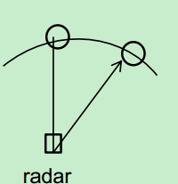
  If there are two objects at different angles(one is 0°,the other is 30 °) with the same range in the following:

Is the signal intensity that the radar receives from the two objects  identical?My understanding is that the object with higher azimuth has weaker signal intensity, is that right?

Thanks in advance,

Regards,

Rata

  • Hello Rata,

    Looks like you tried to attach some pic. Not able to see the pic. Can you try and attach it again?

    -Raghu
  • Hi Raghu,

      If there are two objects at different angles(one is 0°,the other is 30 °) with the same range in the following:

    Is the signal intensity that the radar receives from the two objects  identical?My understanding is that the object with higher azimuth has weaker signal intensity, is that right?

    Regards,

    Rata

  • Hi Rata,

    It depends on the antenna design. 

    For the AWR1642 EVM (check figure 11 of the EVM document - ), the object at 30 degrees (in the horizontal plane) would have a 3dB drop in antenna gain, and consequently a 3 dB decrease in SNR (or signal intensity).

    Regards

    Anil

  • Hi Anil,
    As you said "the object at 30 degrees (in the horizontal plane) would have a 3dB drop in antenna gain, and consequently a 3 dB decrease in SNR (or signal intensity)",then does the configration of dataPathObj->SNRThresholds int the TIDEP-0092 demo depend on the angle? That is to say,if there are two objects at different angles(one is 0°,the other is 30 °) with the same range from the radar, the SNRThreshold value at angle 30 degrees will be half of the object that is at angle 0 degree.
  • Hi,

    In theory, yes, the received signal strength would fall by about 3 dB. (Note that the 'SNR Threshold' is in (scaled) dB, not in linear scale)

    In practice, though, the RCS of a real target (like a car), varies significantly based on its type and orientation. Changes in received signal strength is likely to be dominated by changes in the RCS, and not by azimuth position.

    Regards

    Anil

  • Hi Anil,
    Thanks for your reply, but I still have some questions as below:
    1.In the SRR demo, the CFAR thresholds are varied as a function of range in the following:
    obj->SNRThresholds[0].rangelim = (uint16_t) (6.0f * (float)(1U << obj->xyzOutputQFormat));
    obj->SNRThresholds[0].threshold = convertSNRdBtoThreshold(1, 15.0f, CFARTHRESHOLD_N_BIT_FRAC);

    obj->SNRThresholds[1].rangelim = (uint16_t) (10.0f * (float)(1U << obj->xyzOutputQFormat));
    obj->SNRThresholds[1].threshold = convertSNRdBtoThreshold(1U, 13.0f, CFARTHRESHOLD_N_BIT_FRAC);

    obj->SNRThresholds[2].rangelim = 65535;
    obj->SNRThresholds[2].threshold = convertSNRdBtoThreshold(1U, 12.0f, CFARTHRESHOLD_N_BIT_FRAC);
    What is the theory the configration of the SNR values in dB 15.0f,13.0f,12.0f ?
    2.In the above configration, the range selections are 6.0m and 10.0m, if I want to configrate the range as 20m,30m, 50m, 70m, 80m, how to choose the SNR values?Whether it makes sense to do that.
    3. The peakVal thresholds are varied as a function of range (meant to remove cases of clutter being detected too when we drive the car.) Thresholds were derived from experiments.
    obj->peakValThresholds[0].rangelim = (uint16_t) (3.0f * (float) (1U << obj->xyzOutputQFormat));
    obj->peakValThresholds[0].threshold = (35000 >> obj->log2numVirtAnt);

    obj->peakValThresholds[1].rangelim = 65535;
    obj->peakValThresholds[1].threshold = 0;

    obj->peakValThresholds[2].rangelim = 65535;
    obj->peakValThresholds[2].threshold = 0;
    The peakVal thresholds only satisfy the situation of the range less than 3m, if the range is more than 3m,how to choose the peakVal thresholds? Does that make sense?

    Regards,
    Rata
  • Hi,

    We apologize that no answer was provided for some time.

    Please let us know an answer is still required for these questions or if you were able to answer them based on the code

    thank you

    Cesar

  • Hi Cesar,

    Yes, I still require the answer,can anybody give some support?

    Thanks in advanced,

    Regards

    Rata   

  • Hi Rata.

    Thank you for the questions.

    1. There is no specific theory to select the SNR thresholds. These thresholds were essentially from the different drive tests that we had performed while developing the application. We would look at the detected outputs for a given drive test, and then if we were unsatisfied with the number of detected objects (in a certain range), we would reduce thresholds there. If there were too many detections, we would increase thresholds.

    2. The answer remains the same for peak value thresholds. We had noticed a lot of spurious detections (essentially road-clutter) close to the radar during our drive tests. We noted that while these detections had high SNR, they had low peakVals, and hence we were able to remove them by setting an appropriate peakVal threshold. These spurious detections occurred only close to the radar, and hence only one peakVal threshold was needed.

    If you need to generate these thresholds for your application, my suggestion would be to collect detected object data using either the out-of-box demo (from the SDK) or the SRR demo. From the collected object data, set thresholds based on the statistics of the detected object (either SNR or peakVal).

    Regards
    Anil
  • Thanks for your relpy,I have got it.