This thread has been locked.

If you have a related question, please click the "Ask a related question" button in the top right corner. The newly created question will be automatically linked to this question.

mmWave LAB Object Data Over CAN lab demo not work

Part Number: AWR1642BOOST
Other Parts Discussed in Thread: UNIFLASH, SYSBIOS, MMWAVE-SDK, AWR1443BOOST

Tool/software: Linux

"mmWave LAB Object Data Over CAN" lab demo in "mmwave_automotive_toolbox_2_1_2".

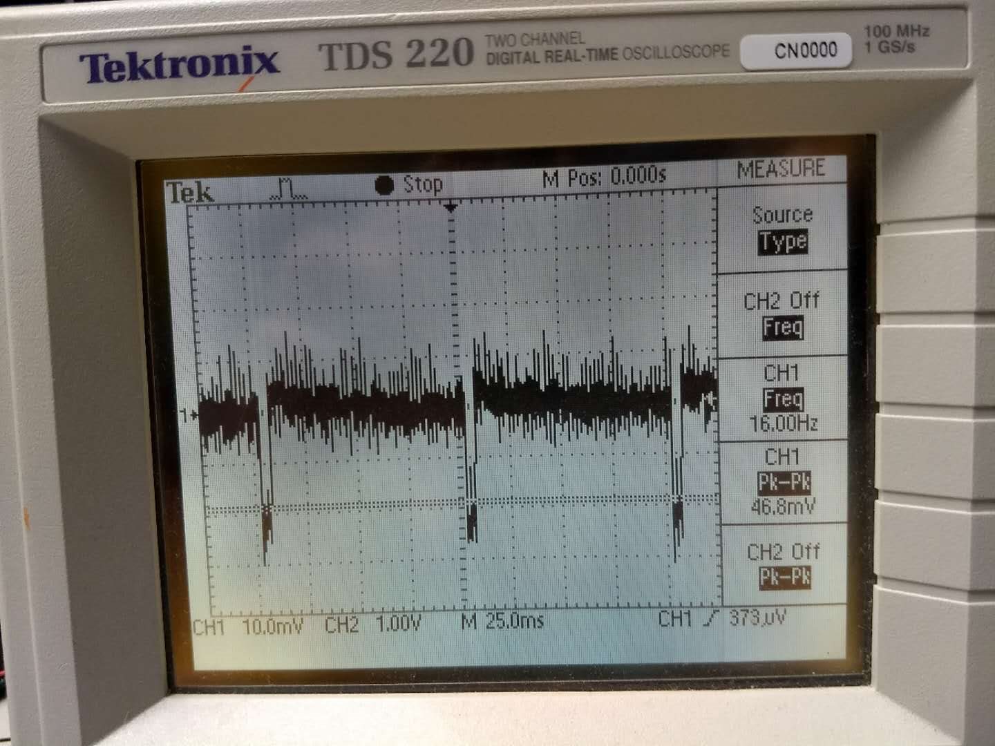
I am trying the mmWave LAB Object Data Over CAN. Before I get a PCAN cable, I setup the system to work with NVidia TX2 which has a CAN port. The system I use is Ubuntu 16.04, the code uses CAN Socket. Anytime when reading the socket, always return -1. Connected to a oscilloscope, I cannot see a CAN signal (see attached, the pulse is only 20mv). I had followed the instructions in section 2.3.3 of document swru508b.pdf to populate R11 and R12 resisters with 0 Ω; and removes R4, R6, R28, and R63 resistors.

 oscilloscope

  • Hello Tao,
    This thread has been assigned to CAN expert, you'll get the response soon.


    Regards,
    Jitendra
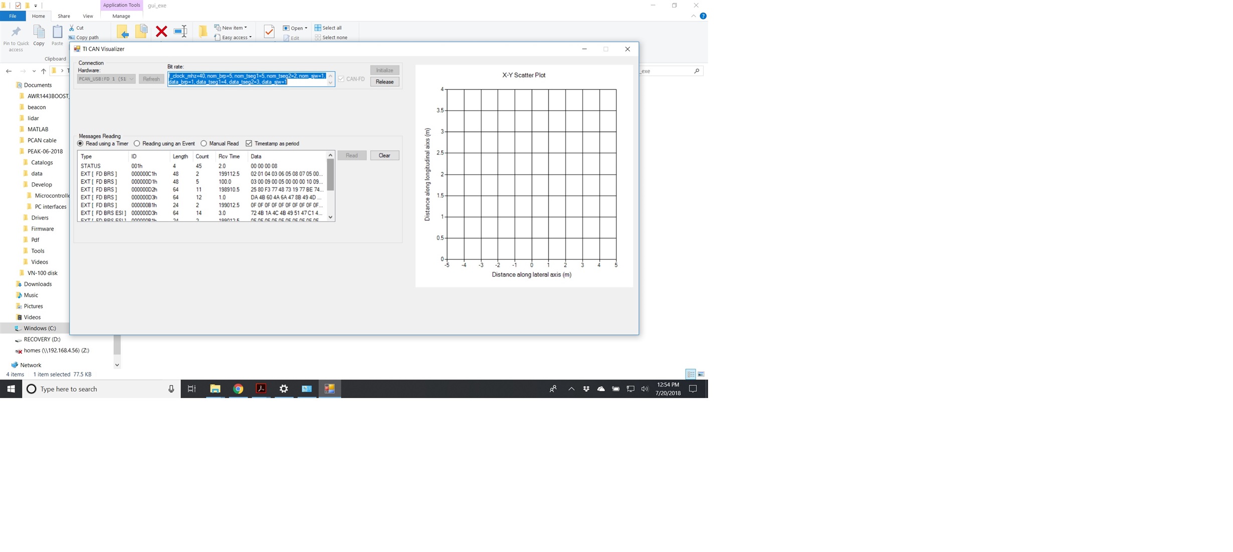
  • Got PCAN cable. Test with my other CAN network, it works. Then connect to CAN bus of AWR1642BOOST, got some messages, then it froze and there is nothing on the X-Y Scatter Plot. Here is a screenshot from "TI CAN Visualizer".

  • Hello Tao,

    Are you using the CCS to download the image to the AWR1642BOOST ? Do you see any error in the CCS console when the freeze happens?

    -Raghu
  • I use Uniflash, and got no error.
  • Hi Tao,
    You are using the pre-built binaries in the release ? or did you build the binaries?

    The default code is for TIDA_01570 . You will need to remove the pre-processor definition "TIDA_1570" from mss_main.c and also from the project properties and rebuild the code for AWR1642BOOST.


    -Raghu
  • Hello Raghu,

    Yes, I use the pre-built binaries in the release as it is taught in the doc "ObjectDataOverCAN_GettingStartedGuide.pdf".

    Would you mind guide me in more details on how to build the binaries? Or is there a reference on how to do that?

    Best,
    Tao
  • Hello Tao,

    The pre-built binaries for AWR1642BOOST in the project works fine on my setup and do not see any issue with those binaries of  loss of CAN communication.  

    To build the project you can import the CCS project and select the "odoc_16xx_mss" and "odoc_16xx_dss" from the "mmwave_automotive_toolbox_2_1_2__win" toolbox.

    The you can do the required modifications to remove the "TIDA_1570" as mentioned in the previous post and rebuild the code .

    Thanks,

    -Raghu

  • Hello Raghu,

    Thanks for your help!

    I notice in the pre-built binary there are two folders: TIDA_1570 and AWR1642BOOST. And after re-flash today, it works fine with the PCAN cable on Windows. I also did the rebuild in CCS, it also works. 

    Now I am trying to make it work in Ubuntu 16.04 using CAN socket. Here is my code for the configuration of the CAN socket and reading of the CAN socket, anything I missed? When read the CAN socket, always get a "-1". 

    int CanSocket::init(std::string ifname)
    {
             struct sockaddr_can addr;
             struct ifreq ifr;

    // Open can socket
    if((s_ = socket(PF_CAN, SOCK_RAW, CAN_RAW)) < 0)
    {
        perror("Error while opening socket");
        return -1;
    }

    setsockopt(s_, SOL_CAN_RAW, CAN_RAW_LOOPBACK, &loopback, sizeof(loopback));

    struct timeval tv;
    tv.tv_sec = 1; // 1 Secs Timeout
    tv.tv_usec = 0; // Not init'ing this can cause strange errors
    setsockopt(s_, SOL_SOCKET, SO_RCVTIMEO, (const char*)&tv, sizeof(tv));

    strcpy(ifr.ifr_name, ifname.c_str());
    ioctl(s_, SIOCGIFINDEX, &ifr);

    addr.can_family = AF_CAN;
    addr.can_ifindex = ifr.ifr_ifindex;

    if(bind(s_, (struct sockaddr *)&addr, sizeof(addr)) < 0)
    {
        perror("Error in socket bind");
        return -2;
    }

    return 0;

    }

    int CanSocket::readCAN(struct can_frame *frame)
    {
             int nbytes;

    if (getCANKey())
    {
         nbytes = read(s_, frame, sizeof(struct can_frame));

         if (nbytes < sizeof(struct can_frame))
         {
            return -1;
         }

         releaseCANKey();
    }
    else
    {

          return -1;

    }

             return nbytes;

    }

    Best Regards,

    Tao

  • Tao,

    We do not have a Linux offering.

    Thanks,
    Raghu
  • Hello Raghu,

    I understand the Linux no offer. Would you mind guide me on the protocol of how the mmWave will send the CAN frames, and on the computer side, what should I do to read the CAN frames? Do I need to send some CAN frame to activate the CAN frames sending from mmWave? Or should I send some acknowledge frame to mmWave? Is there any timing for the reading of the CAN bus on the software level?

    Best Regards,

    Tao Wang

  • Hello Tao,

    Please refer to the function "Get_CanMessageIdentifier()" which does the mapping of the demo output message with the CAN message identifier. This should give you a fair idea of the different CAN message sent out of the device. Also you can refer to "MmwDemo_mboxReadTask()" task function which takes care of transmitting the CAN messages based on the demo output message.

    Hope this helps your understanding of the messages sent by the device.

    -Raghu
  • Hello Raghu,

    Thanks for your help.

    Now, I can read out the data from the CAN bus after revising configuration of CANSocket. I got neat data repeated like:

    repeat      CAN id               data length

    1              c1              48

    1             d1               08

    1             d1               32

    1             d2               08

    8             d2               64

    1             d3               08

    8             d3               64

    1             d6               08

    1             d6               24

    1             b1               04

    I go into the code but cannot figure out how is the data arranged, would you mind guide me to the protocol or the data format? I need to figure out what is the reading of the sensor. 

    I also would like to do the compare between the CAN frame data and the UART data (mmwave_industrial_toolbox_2_4_0/labs/lab0006). 

  • Hello Tao,

    The data sent by the device is exactly the same in both the cases ie when the interface is CAN and UART. For the CAN interface , we have just appended the message identifier to the payload before transmission.

    You can refer to the MMWAVE-DEMO-VISUALIZER code(JScript) and refer to routine processDetectedPoints() in the mmwave.js . This provides the processing of the detected points. For mapping of this code with the SDK based code(CAN code) look at the function Get_CanMessageIdentifier() that maps the CAN message identifier with the mmwave demo output.

    BR,
    Raghu
  • Hello Raghu,

    I made the demo work with the pre-built binary at last. Now I need to do some work to make it fit in our application. So I tried to use the debug mode of CCS 8.1 on mmWave. I flashed the ccsdebug image into mmwave, and built the project as you recommended. I got errors or terminated.

    On Linux (Ubuntu 16.04) I got:

    *****************************************************************************************************************************

    [Cortex_R4_0] **********************************************
    Debug: Launching the Millimeter Wave Demo
    **********************************************
    Debug: MMWDemoMSS Launched the Initialization Task
    Debug: SPI Instance @0800d0a4 has been opened
    readData = ffffffff
    readData = ffffffff
    readData = ffffffff
    readData = ffffffff
    readData = ffffffff
    readData = ffffffff
    readData = ffffffff

    ******************************************************************************************************

    On Windows 10 I got:

    *******************************************************************

    [Cortex_R4_0] Exception occurred in ThreadType_Main.
    Main handle: 0x0.
    Main stack base: 0x8003360.
    Main stack size: 0x1000.
    R0 = 0x00000000 R8 = 0x00000000
    R1 = 0x00011354 R9 = 0x00011c74
    R2 = 0x0001b561 R10 = 0x0f2e0000
    R3 = 0x08004254 R11 = 0x00000395
    R4 = 0x0800428c R12 = 0x0001583d
    R5 = 0x00000001 SP(R13) = 0x08004268
    R6 = 0x08003352 LR(R14) = 0x00015843
    R7 = 0x08003340 PC(R15) = 0x00013b20
    PSR = 0x400c019f
    DFSR = 0x0000080d IFSR = 0x00000000
    DFAR = 0x07ffffec IFAR = 0x00000000
    ti.sysbios.family.arm.exc.Exception: line 209: E_undefinedInstruction: pc = 0x00013b20, lr = 0x00015843.
    xdc.runtime.Error.raise: terminating execution

    *********************************************************************
    It seems stuck at BIOS_start()? Anything I missed?

    Best Regards,
    Tao
  • Hello Tao,

    You need to remove the "TIDA_1570" definition from the mss_main.c and the makefile. You are compiling the code for a different variant of the EVM.

    Please re-compile the code with above modification to use the demo on the AWR1642BOOST.

    Thanks,
    Raghu
  • Hello Raghu,

    Thanks for your help. I only remove TIDA_1570 in the code. I find it also in the compiler options. I remove it, and it works in debug mode with CCS.

    I tried also the SDK demo for xWR16xx, but it fails. This demo is imported from "Resource Explorer/mmWave Sensors/Industrial Toolbox - v.2.5.1". I just remember that my AWR1642BOOSTE is not ES2.0, and it is not supported by SDK 2.0, while the SDK demo for 16xx in Industrial Toolbox v2.5.1 requires the SDK 2.0, am I right? Is there a SDK demo project for SDK 1.2?

    Best Regards,

    Tao Wang

  • Hello Tao,

    The release notes of the demo will let you know the SDK versions it supports. You are right the TIREX project is for a SDK version 2.0.0.4

    If you need a mmw demo working for MMWAVE-SDK for version 1.2 you can download the MMWAVE-SDK-LTS and check the demo. 

    Thanks,

    -Raghu

  • Hello Raghu,

    How are you!

    I am trying on making CAN works on AWR1443BOOST, got stuck at waiting for the sensor_START event to acquire the semaphore for reading the sensor. Would you mind looking at my another question topic at: e2e.ti.com/.../2672497

    Best Regards,
    Tao
  • With comparing of the "cli.c" in the SDK and in the ODOC(Object Data Over CAN) demo, I find the way in the demo used for CAN FD: bypass the cli and make a table for the configuration of the radar. But the debug always crash at trying to execute the command "sensorStop" which is the first command for the radar configuration. Is there any extra initialization for the commands to the radar? Or there is some timing for commands to radar?

    As the change of the code cause overflow of program memory, I comment off "Initialize LVDS streaming components", will this affect the command sent to radar?

    Tao

  • Hello Tao,

    The ODOC is for AWR1642BOOST EVM and it is not intended to work in the AWR1443BOOST EVM. 

    The AWR1443BOOST only has a CAN interface and does not have any CANFD interface . 

    Thanks,

    Raghu