This thread has been locked.

If you have a related question, please click the "Ask a related question" button in the top right corner. The newly created question will be automatically linked to this question.

OPT101 ambient compensation feedback problem

Other Parts Discussed in Thread: OPT101, OPT301, OPA827

Hi, 

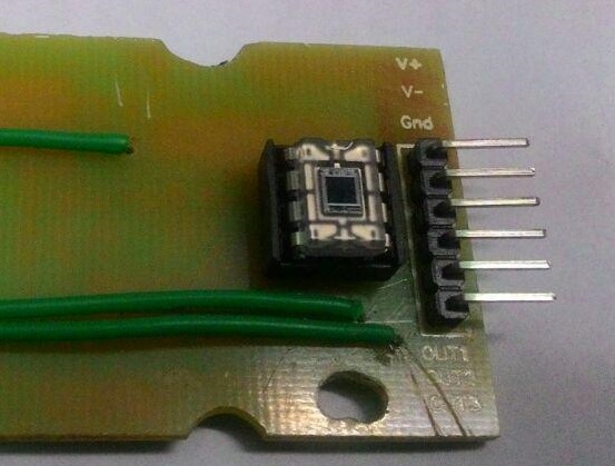
We from Eltron Wireless, initiated R&D work on distance measurement system with working range up to 40m. The system uses infrared transmitter LEDs (OP293A) which transmits infra-red ray in terms of short pulses (50 uS ON time and 1250uS OFF time) and is reflected back by any object and is received by infrared receivers (OPT101 from Texas Instruments) and accordingly the waveform is seen on DSO.

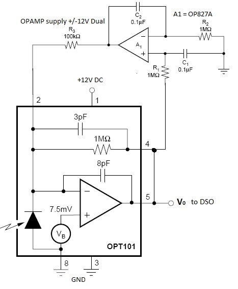
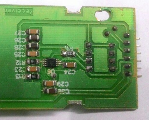
Now we are focusing on receiver circuit in which we are facing some problems. The schematic is shown. The OPT101 i.e. the photo-diode with trans-impedance amplifier receives the incoming IR pulses and the output is stable at 3V (approx) pulse from object distance 3m approx and it is working fine. To compensate ambient light (to use in outdoor) we have used feedback mechanism using OPA827 OPAMP as shown in datasheet of OPT301 DC restoration circuit to avoid ambient light.

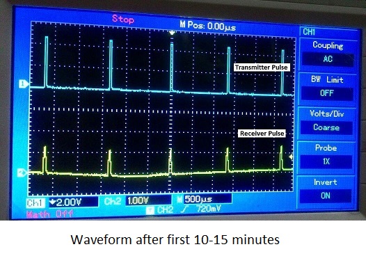
Now the problem we faced is that when feedback path consisting of OPA827 is connected then the ambient light compensation is perfectly happened but the waveform is not stable. Actually the waveform peak value is varying time to time i.e. after powering upthe output is say 3V pulse, after 10-15 minutes it considerably decreased to less than 1.5V peak (for example) and it is slowly varying with respect to time.

The assembly of PCB is well arranged and other wiring matter is perfectly intact and there is no chance of loose connection related issues. All components used are of SMD types. The problem of un-stability vanishes when feedback network is absent. But in that case ambient light compensation was not done naturally.

So please suggest suitable modification or recommendation to avoid the problem for our requirement as described.  

  • DHRITINANDAN,


    We will look into this tomorrow morning.  In the mean time,

    Is the decrease of intensity after 15 minutes repeatable?  When you say it varies slowly with time, does it ever increase again, or go considerably lower?

    Is there another device on the board that is generating heat that could be affecting one of the active or passive components in the circuit?

  • Actually 10-15 minutes after powering up the peak response voltage decreases from 3V to less than 2V approx. and it very slowly decreases considerably low if we keep powering on for say 1 hour or 2 hour. But if we switch it off for say 15 minutes and again power up, then it again resumes from 3V around. I checked the heating issues of the on-board components and seen that there is no unnatural heating effect on the PCB. Everything remains in room temperature.
    When I execute the experiment on an completely other PCB with all other set of components, the problem remains similar.
    The pulse height is very crucial for me because with the pulse height, I want to have an estimate of the distance of object in front of the sensor assembly.
    Please suggest.
  • This is an unusual issue, I will confer with my colleagues and see what we can figure out.
  • Hi,

    Have you kindly pointed out any issue for my case? I am worried about the unusual behaviour of my circuit and I am forced to stop my development further.

    For convenience I would like to show you the actual schematic and PCBs. Is there any issue that is coming out from feedback network?

    We have used OP827A OPAMP using dual +/-12V supply. Or recommend suitable feedback circuit using suitable OPAMP for OPT101 feedback network for proper ambient light compensation.

    Please see the schematic and comment.

    The files are attached. Thanks.

  • Thank you for all the information and scope shots. I apologize for the delay in response - I am conferring with my colleague about it and I hope to have some information for you tomorrow.
  • Hi,

    Still waiting for our valuable reply...

    Thanks

  • DHRITINANDAN,

    I apologize, I got very ill the past few days and couldn't get to the office.  I sent your question and data and schematic to the designer of the OPT101, and I also set up my bench test board to test your circuit to see if I can replicate the issue.  I will let you know my findings tomorrow.

  • Dhritinandan,

    We set up the circuit and after a bit of adjustment, believe that you need put a bit of a negative supply voltage on pin 3. The circuit from the OPT301 data sheet expects some headroom provided by V-, where the OPT101 is not shown in that particular configuration with pins 3 and 8 tied together and to ground. Try applying a -3V supply to pin 3 (but still GND to pin 8) and see if your circuit stabilizes. On our test circuit, we saw very favorable results.