This thread has been locked.

If you have a related question, please click the "Ask a related question" button in the top right corner. The newly created question will be automatically linked to this question.

OPT8241&OPT9221:Reference circuit for driving LEDs

Other Parts Discussed in Thread: OPT8241, OPT9221, TPS2559

Hi all,

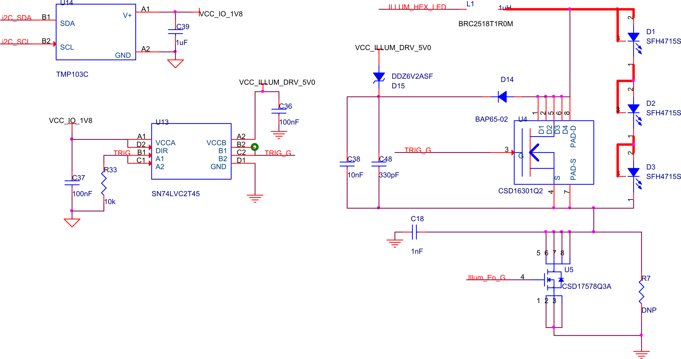
The OPT8241 CDK provides the reference for Laser diode driving,By the way,what the part of "HEX_LED ckt" is used for?

Can you provide me with some reference about LED drive circuit?

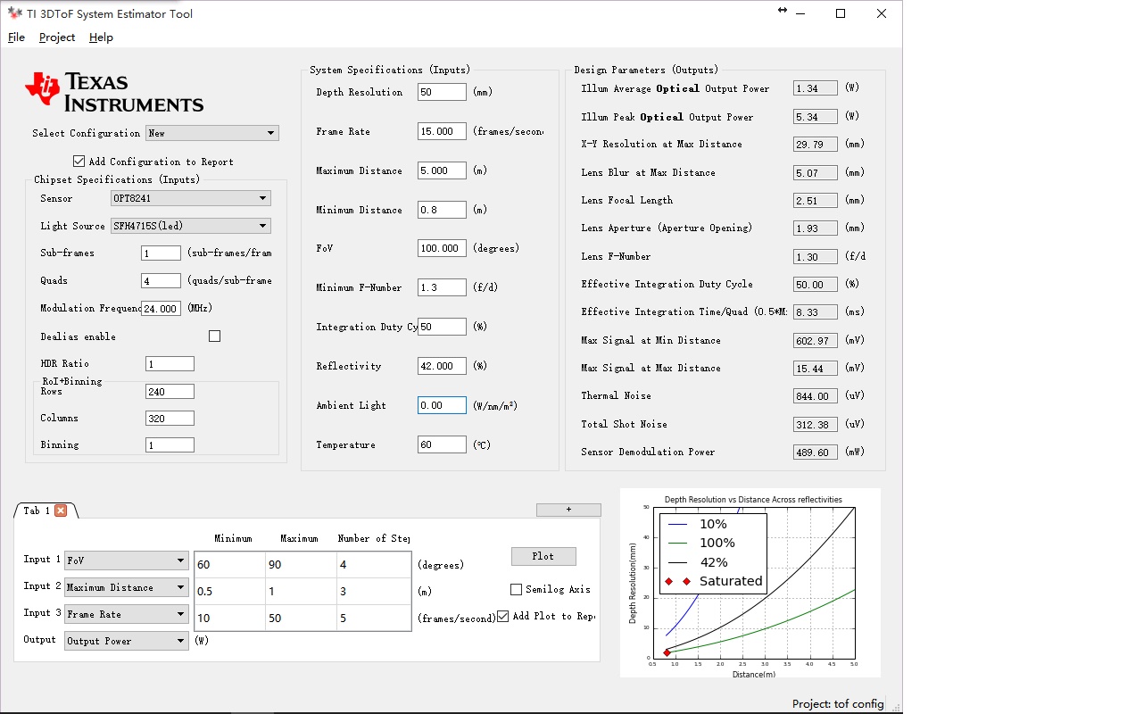
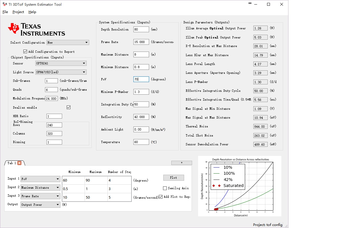
The input voltage is 5V,LED 4715S,FOV 100deg,Max dis 8m or farther.

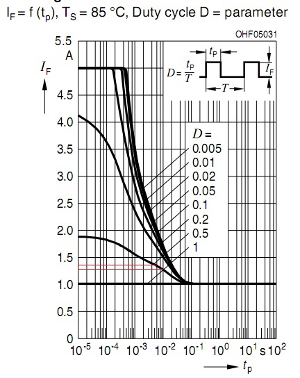
can 2 LEDs do this (4715S  VF 3V,IF 1A)? Does "Path Delay Correction" needed here?

  • Zuan,


    "HEX_LED" circuit is not used in the CDK. All those components are not populated on the board. We only use Laser diode based driving on the CDK.

    For deciding on the number of LEDs, it depends on a number of parameters. I would recommend that you use the system estimator tool to understand the optical power requirements for your application.
    You would have to use modulation frequencies of up to 24MHz for LEDs. Laser diodes can give you a higher modulation frequency of up to 80MHz. For relatively longer range applications like 8m, you might have to use the "dealiasing" feature of the chipset. Details on the tool are given in the user guide under the "Help" tab.
    SFH4715S can be overdriven to more than 1A if we pulsed driving at duty cycles<1. The LED datasheet provides information on the maximum current for a given duty cycle. It is preferable to overdrive the LEDs to get advantage on cost.

    Path delay correction helps compensate for temperature dependent phase offsets. It is possible to compensate for the temperature based delays with a feature in OPT9221. OPT9221 can assume a linear relationship between the temperature and the phase offset and correct for the same. So it is not necessary to do path delay correction in your system. However, you may choose to implement a correction mechanism.

    Please let me know once you have decided on the spec in the system estimator tool. We can work forward on the number of LEDs, power supply, drive circuit etc thereafter.

    Regards,
    Subhash

  • Hi,Subhash:

    I list the result of the tool as below.

    If a depth resolution of 1.5% instead of the requirement of 1% is used,the peak power will below 10W.

    according to the datasheet of 4715S,the IF = 1.8~1.9A when the duty cycle is 50%,and VF is about 3.1~3.2V  ,so the power should be about 5.7W.

    Maybe,there shold be three LEDs for better extensibility.

    Regards,

    Zuan.

  • Zuan,

    The LED datasheet has 2 parameters on which the maximum current is dependent. It is the pulse time and the duty cycle. At 24MHz, the pulse times will be so small, they are out of the lower limit of the data given. You would have chosen another limit in the System Estimator tool called "Integration Duty Cycle".

    Integration duty cycle is (Integration Time / Quad Time) for the usual timing waveform depicted in the diagram above. As the high frequency modulation has a very short pulse time, you should consider the Integration Time as your pulse time and decide upon the current according to that. You can actually drive the LED at double that current to get the peak optical power. You just need to make sure it is less than the absolute maximum current of 5A for SFH4715S. The LED can get heated at such high currents and duty cycles. It is advisable to use good heatsinking or an aluminum substrate PCB for dissipating such high heat levels

    About the lens, do you think you can use an 87 degree Diagonal FoV, F1.1 lens which is used in the Tintin CDK? This would greatly improve your performance spec/reduce the number of LEDs required.

    About the ambient, is your application in outdoors sunlight? You would have to enter the expected amount of light spectral power around the 850nm wavelength. This light will affect the way your system behaves.

    In absence of sunlight, it is preferable to have fewer sub-frames if Thermal Noise is more than the shot noise. So I suggest the following configuration:

    This requires Illum Peak Optical Output Power of 6.6W.
    Integration Time = 5.5ms
    Ipulse  according to the datasheet = ~1.25A
    LED peak current = 2 * Ipulse = 2.5A
    LED peak power for 2.5A from datasheet = 2.5 * 1070mW = 2.675 W
    Number of LEDs = 3

    In your calculations, I noticed that you are taking the electrical power of the LEDs. The tool can calculate the Optical power of the LEDs. So, you would have to refer to the datasheet to see how much current has to be driven for the required optical power.

    Please let me know if the choice of lens is acceptable to you. I feel that the system will be more optimised for this lens. Also, the system response is expected to change a lot if it is in presence of ambient sunlight. Please consider that as well.

    Regards,
    Subhash

  • Hi Subhash,

    The picture of configuration is broken,can you fix it ?

    Thank you.

    Regards,

    zuan

  • Zuan,

    Sorry about that. It should show up now.

    Regards,
    Subhash
  • Subhash,

    First,I'm really taking the electrical power of the LEDs confused with optical power,I meant to confirm the parameter.

    About the duty cycle,I think the accurate value is,"50% * Integration Duty Cycle".And in my calculation,I took the "Integration Duty Cycle" approache 100%.

    Your calculation method of LED peak current inspired me,I'll check it.And we have some experience in radiating design of LEDs.

    About the lens,I kown larger the aperture will improve my performance,I just choose a universal lens in our industry.I'll search for the lens more suitable in our current suppliers. My colleague told me that there are F1.3 lens,the focal length could be 4mm or 6mm.Please take the F1.3 for calculation.

    About the ambient,we really expect the camera to be able to work well in outdoors sunlight,but it should take very high optical power due to the Estimator tool,and we expect it to be able to work indoors first.
    I have no idea about the expected amount of light spectral power around the 850nm wavelength,what the value should be when the camera works under High/Low-intensity diffused sunlight/indoor/at the door with some sunshine coming in.Can you provide me some reference data.

    In fact,there are two applications,wide field view with shorter distance,and longer distance with a bit narrow field permissible.

    Zuan
  • Zuan,

    Just to make it clear, Optical Power is the light power emitted by the LEDs. So Optical Power = LED Efficiency * Electrical Power.

    Please let me know if the LED peak current calculation is clear.

    The lens choice is important for our system as you can see. The F number and the transmission efficiency decide the system performance to a great extent. We can give you a reference for an F1.2 lens with 3.3 mm focal length if required.

    We are not the experts on the solar spectrum distribution, data, etc. For a starting point, there is some survey data on this website. I am guessing that the data in the website is for outdoors. For indoors, you would have to consider the lighting. Incandescent and any other such light sources would have some appreciable spectral power in 850nm range. For diffused sunlight next to a door, it might be sufficient to consider a scaled version of the data in the website.

    I would also suggest that you treat the longer range and the short range applications separately. It might be easiest to come up with separate requirements for each of the application. We can finally try to get a common hardware configuration which works for both applications (if possible).

    Regards,
    Subhash

  • Subhash

    Thank you,I have got it.

    The pulse times are so small that It seems to be continuous ,while the equivalent current is half of the peak current.Then I can consider the Integration Time as the pulse time in a Quad Time cycle.

    application 1 : FOV 100 deg & 5m

    Integration Time = 8.33ms
    Ipulse  according to the datasheet = ~1.25A
    LED peak power for 2.5A from datasheet =1.25*2* 1070mW = 2.675 W
    Number of LEDs = 2 (5.34/2.675)  but the Number  3 is better suited than 2; If lower the depth resolution or the max distance abit, 2 LEDs would be ok.


    application 2 : FOV 70 deg & 8m

    Integration Time = 5.56ms
    Ipulse  according to the datasheet = ~1.3A
    LED peak power for 2.5A from datasheet =1.3*2* 1070mW = 2.782 W
    Number of LEDs = 2 (5.03/2.782) .

    Now can you tell me about the circuit for driving 2 or 3 LEDs?

    Zuan

  • Zuan,

    You could use a similar Inductor + MOSFET + Illuminator configuration as the Hex_LED circuit in the OPT8241 CDK. Except, you would be having 3 LEDs instead of the 6 LEDs. So the schematics, in short, would look like this:

    Each LED will have a Vf a little greater than 3V. Combined Vf of the 3 LEDs plus the overhead to drive the parasitic inductance will approximately between 10V to 12V.

    The power source that supplies current to ILLUM_HEX_LED has to be a constant current source. This current source would have to sustain an output voltage of approximately 0.5*Vf. This effect is because the inductor L1 and the MOSFET U4 together make something like a boost converter with 50% duty cycle. So you will need approximately 6V as the current source output voltage. For 2 LEDs, you will need a lower voltage as the current sosurce output voltage.

    We would recommend that you use TPS2559 as the current regulator. You can refer to the 'Linear' page in the schematic 'OPT8241-CDK-EVM IB 10-50' to see the implementation of the same. You might have to use a buck converter or a boost converter to supply required input voltage to TPS2559. To improve efficiency, you could set your desired current levels and then carefully adjust and minimise the voltage headroom across TPS2559 in a prototype PCB.

    Please note that the system estimator tool assumes that all of the LED power is going into the FoV of the camera. It does not account for the light which lost outside the FoV. You would have to build in that factor of safety in your actual system design. Also, the LED output radiance is not constant across the FoV. The center will be more brightly illuminated as compared to the corner of the FoV. You will see a proportional variation in the performance.

    Regards,
    Subhash

  • Subhash

    What's about the "Path Delay Correction"?

    Maybe I can reserve it on the board,is it same as the CDK?

    Thank you!

    Zuan.

  • Zuan,

    Path delay correction would be similar to the CDK. You would, however, have to make some changes. LED forward voltage can be more than 3V. You would have to be careful to not exceed the comparator common mode limits. Making use of a resistive divider would bring the voltage down to detectable levels.

    Also, you would have to ensure the voltage overdrive for both the comparators is matched.

    Regards,

    Subhash

  • Subhash,

    Another question, If I use an aluminum substrate PCB for dissipating the heat of LEDs,only several LEDs are on the board usually,then the board connect to the LED driving board with a cable.Can they work well at such a high frequency?

    Zuan
  • Zuan,

    You raise a valid point. Aluminum substrate PCBs might not be built for impedance control.
    We are not the experts on this in general. However, we have used a board with cables which are not impedance controlled. OPT8241 CDK is one such example. We have also had some customer implementations which make use of aluminum substrate PCB. So I think it is possible to build such a system.
    You would have to be careful of the reflections in the ILLUM_P/ILLUM_N, COMP_MOD_REF, COMP_MOD_FB signals. The easiest way is to just minimise the wire lengths. If you are using LEDs, you might not exceed 30 MHz or 35 MHz.

    Regards,
    Subhash
  • Subhash

    Maybe you get me wrong,What I mean is, anode and cathode of the LED series, maybe also a current detect signal which goes to the comparators,go through the cables. While the other components like Inductor / MOSFET/comparators are on the LED driving board.

    Zuan
  • Zuan,

    I understand now. It is good to have only signal and power supply connections over the cable wires. That is how we have done it in the OPT8241 CDK.
    The inductors, MOSFETs, and MOSFET driver, etc should be on the same board and placed close to each other.. The layout should be optimised to get ultra low parasitic inductance.

    Regards,
    Subhash
  • Zuan,

    Sorry for the delay in response.
    Path Delay Correction will be the same as on the CDK. You would have to be careful with the voltage swing of the LED as it is more than the voltage swing of the laser. As long as the comparator input can take that voltage, you should be ok.

    Regards,
    Subhash
  • Hi Subhash,

    "LED peak power for 2.5A from datasheet = 2.5 * 1070mW = 2.675 W"

    Q1: I am confuesd about 1070 , i am not find this information on the SFH4715S spec, Can you tell me what it means?

    Thanks&Regards

    None
  • Hi None_feiyu

    From page no:2 of the SFH4715S datasheet,

    Total radiant flux for 1A current (100uS pulse) = 1030 mW.
    Hence , if you are allowing a current of 2.5A, the optical power output = 2.5*1030 = 2.575 W

    Thanks
    Nithin
  • Hi Nithin,

    Thanks for you information,I got it.

    Thanks&regards

    None