This thread has been locked.

If you have a related question, please click the "Ask a related question" button in the top right corner. The newly created question will be automatically linked to this question.

AFE4404EVM: AFE4404

Part Number: AFE4404EVM
Other Parts Discussed in Thread: AFE4404

Hi,

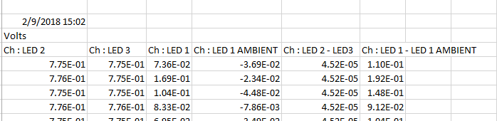
I am using AFE4404 GUI. Furthermore I am using OSRAM optical sensor on AFE4404 sensor board by installing the required resistors.

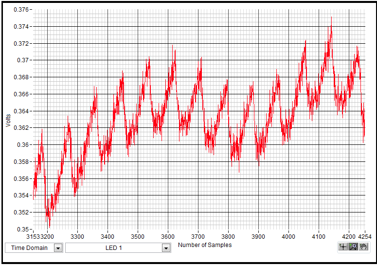
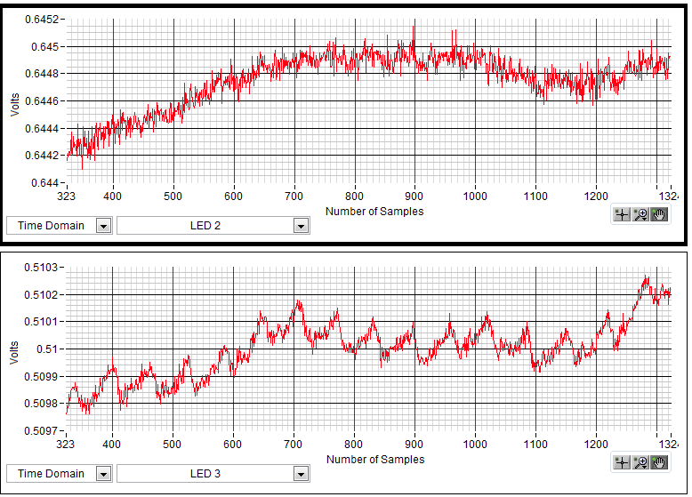
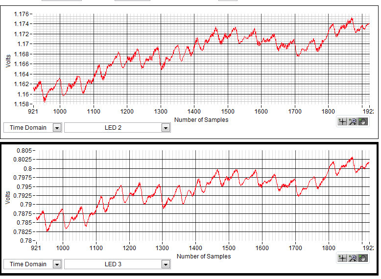
Please guide me how can I choose the optimal values for TIA Gain and Cf. Do I have to observe the waveform of LED1 to observe the heartbeat?

Thank You

  • Hi Qasim,

    TIA Gain (i.e. Rf) and Cf should be chosen such that Rf*Cf is 1/10th of Sampling period. You can increase the Rf such that you get the decent signal required by post processing block and for that Rf choose the Cf such that Rf*Cf is 1/10th of Sampling period.

    Yes, to observe the heartbeat you have to observe the phase where you fire the LED ( depending on the setting it can be LED1/LED2).

    Regards,
    Prabin
  • Hi Prabin,

    Thanks for your feedback.

    I need a little bit more information. Can you explain the difference between PRF and sampling period. Further, why I am not able to increase the duty cycle more than 10% in GUI?

    And how can I determine the magnitude of current to be added or subtracted?

    I have attached the waveform that I am observing. can you tell me what should i do to make the wave smooth. Right now, the value of the parameters are shown below

    PRF=110Hz

    Duty Cycle = 10

    Rf=25K Cf=5pF

    LED1 = 30.4

    LED2 = LED3 = 0

    And I am using OSRAM sensor not NJL5513R sensor.

  • Hi Qasim,

    PRF and sampling frequency are same.
    Yes, duty cycle is limited to 10% in the GUI. Reason for this limitation is that you will not gain any thing by increasing the duty cycle. However greater duty cycle will directly increase your power consumption. LED on time of few hundreds of uS should be sufficient .
    To make your waveform smooth you have to avoid noise pick up ( mostly 60/50 Hz from mains). So try running the EVM from the battery powered laptop without having any electrical contact with the body.
  • Hi Prabin,

    By running EVM from battery powered laptop did smooth the wave a lot. The snapshot of the waveform I sent was taken through finger tip. I am not able to get the same waveform from wrist.
  • Hi Qasim,,

    For the wrist you may have to program higher LED current as blood vessel might be deep under the skin.
    Please also note that increasing LED current, the DC of the signal will increase ( may even saturate the ADC). So you have to use the offset cancellation DAC to subtract out the DC. To do so just estimate the DC current ( Average of output/(2*Rf)) and program the same current in the Offset DAC with the polarity bit set to 1 ( to subtract).
    With the DC cancelled , you can use the higher TIA_Gain ( i.e. Rf) to amplify the PPG signal.

    Regards,
    Prabin
  • Hi Prabin,

    Does LED1 Ambient represents the current of photodiode? To estimate the DC current do I have to take average output of LED1 or LED1 Ambient?
  • Hi Qasim,

    LED1 Ambient represents current of the photodiode when the LED is off. This can be due to indoor lighting or light present in the environment.
    To estimate the currents for the DC cancellation you have to take average of LED1 and LED1 Ambient separately and individually subtract them in respective phases.

    Regards,
    Prabin
  • Hi Prabin,

    Thanks for all your responses. I need to ask that where can I find the wrist wrap that is shown in the picture below. I know its not the right question to ask here but I am unable to find it. So If you can help me out, I would be very thankful to you. 

  • Hi Qasim,

    You can use any other ordinary elastic band to hold the sensor.
    Just make sure it blocks the ambient light.

    Regards,
    Prabin
  • Hi Prabin,

    I used other ordinary elastic band but they are efficient in holding the sensor as well as blocking the ambient light. That's why I wanted to buy the similar one.
  • Hi Qasim,

    That band was made in house, so we don't have the part number.
    You can search for ESD wrist strap and use only the band part of it.

    Regards,
    Prabin
  • Hi Prabin,

    I think that I need your help again. I have acquired a good PPG signal using green led only. The estimated heart rate from the signal was same as ground truth heart rate.

    Now I am trying to estimate SpO2 level using red and IR led. Green led is off. By tuning the parameters as

    LED 2 current = 30mA

    LED 3 current  = 20.8mA

    TIA Cf x TIA Gain = 5pF x 10K

    I get the following waveform. LED 3 is a typical ppg signal but I am not getting the write waveform on LED2

    Please guide me how can I get a typical ppg signal on LED 2 as well.

  • Hi Qasim,

    Is LED2 a Red LED?
    Can you first try at finger tip? This will make sure register settings are correct.
    You can also try to filter out the high frequency noise by doing moving average of few samples.

    Regards,
    PRabin
  • Hi Prabin,

    I got the following response at finger tip with parameter set as follow

    LED 2 current = 19.2mA

    LED 3 current  = 14.4mA

    TIA Cf x TIA Gain = 2.5pF x 100K

    TIA Cf_SEP x TIA Gain_SEP =2. 5pF x 10K

    OFFDAC LED2 = 6uA

    OFFDAC LED3 = 6uA

    After that I tried to get the waveform at wrist. I had to increase the LED2 Current to 25mA with other parameters same. I import the data on MATLAB and applied moving average filter. The results are shown below. Plots are from the MATLAB

    Still the signal is not fine. You can observe that the AC level of the signal is very low and signal is noisy also. Please what should I do further to get a good PPG signal as I got at finger tip.

  • Hi Qasim,

    Amount of the PPG signal being received totally depends on sensor location on the body ( due to obvious biological factors).
    That being said, following are my observation after seeing the waveform.
    1) DC level of the signal is ~0.73V. Are you setting the OFFSET DAC to negative -6uA or 6uA? Try to cancel as much DC as you can.
    2) Increase the LED current, so that more light can penetrate inside the skin.
    3) Can you look at the frequency spectrum of the signal. This is to find the noise source, hope you are not picking AC mains.
    4) Can you use LED-Ambient instead of just LED phase.

    Regards,
    Prabin.
  • Hi Prabin,

    Thanks for your response. Answer to your questions are as follows
    1) OFFSET DAC is set to -6uA.
    2) I will increase the LED current and check whether the results are better or not
    3) I don't think so I am getting the AC mains because during reading I operate my Laptop through battery by disconnecting the charger.
    4) Actually I am using your GUI for evaluation, so Is there any way that I can access LED 2 and LED 3 ambients. Becuase the log data contains only LED 1 ambient and other are LED phase only.
  • Hi Qasim,

    Out of 4 phases available, the phase where LED is off has the ambient information.
    You can save all 4 phase data using the data and subtract the Ambient in the excel sheet yourself.

    Regards,
    Prabin
  • Hi Prabin,

    As you can see the channels that are available. Is LED 1 Ambient represents the ambient data for all LEDs? Like I have to do this LED2 - LED1 Ambient and LED3 - LED1 ambient. Is that right?

    Furthermore, why the TIA_SEP_GAIN affects the DC level of LED3, as mentioned in the GUI TIA_SEP_GAIN is for LED2.

  • Hi Qasim,

    Yes, you are correct regarding Ambient subtraction.
    When you enable separate gain, LED2 and LED3 will have one gain and LED1/LED1 Ambient will have another setting.
    For further detail please refer section 8.3.1.2 of the datasheet.

    Regards,
    Prabin
  • Hi Prabin,

    I am able to estiamte the heart rate and spo2 through finger and wrist as well but there is one thing i need to ask. During testing I found that sometimes LED2 and LED3 saturates at 0.6. Why is that so? If it were to saturate then it should saturate at 1.2

  • Hi Qasim,

    Can you please read the output registers ( i.e 42d to 47d ) at those stuck state?
    What exactly causes this? Do you change some registers that puts the AFE in this state?
    Also do you see such saturation when running the EVM default register settings?

    Regards,
    Prabin
  • Hi Qasim,

    I'm closing this thread since there hasn't been any followup in a while. If you have further questions feel free to post them and the thread will automatically reopen.