This thread has been locked.

If you have a related question, please click the "Ask a related question" button in the top right corner. The newly created question will be automatically linked to this question.

What will be the peak frequency of valid start signal for TDC7200 under one start-one stop situation?

Other Parts Discussed in Thread: TDC7200

What will be the peak frequency of valid start signal for TDC7200 under one start-one stop situation? I mean, if the TDC7200 works under 16MHz and the MUC can work under 25MHz, it still need some delay to process the data, thus, what will be the max frequency for a valid start input?

  • Here's a rough calculation:

    1 measurement period = Trigger to Start time + Start to Stop1 time + Stop to INTB time + Results Readout time

    Trigger to Start time:

    5ns (typical)

    Start to Stop1 time:

    Depends on your Application: Assume Mode1 operation with Start to Stop1 time of 200ns

    Stop to INTB time:

    Assuming 2 cycles calibration period and 8MHz clock it is equal to

    (2+1) clock cycles calibration + 4 clock cycles synchronization = 875ns

    Results readout time for 1 Stop:

    Assuming 20MHz (50ns) SPI clock and Mode1 operation, you need to read out Time1, Time2, Calibration1 and Calibration2 (each 24bit) registers

    = 50ns x 4 x 24 = 4800ns

    Hence, 1 measurement period = 5 + 200 + 875 + 4800 = 5880ns = 5.88us.

    This translates to 170kHz for Start frequency.
  • Hi Vishy,

    Thank you very much for your help. A further question will be what will happen if we use a 1MHz which is higher than the valid frequency (170KHz) but smaller than the frequency of the TDC (8MHz)? Thank you again for your help.

    Bests,

    Chris
  • Chris,
    TDC7200 starts looking for START pulse after asserting TRIGG. Ideally, TRIGG output of TDC7200 should be monitored and then START has to be asserted. Otherwise, device can miss START.
    Thanks,
    Vishy
  • Vishy,

    Is it correct to say if the TDC7200 receives start or stop pulses during the microprocessor is still fetching the data from the last measurement, the start or stop pulses will be ignored, because the device needs to be prepared by an init-instruction (TRIGG) before starting the next measurement? Then what will happen if a start did not followed with a stop, but the next start followed with a stop? And the time between the two starts is within the measurement range and will the chip still can be triggered by the next start and then the chip record the time between the next start and the following stop?

    Bests,

    Chris
  • By the way, in the hand book of TDC7200 8.4.6 part, the TRIGG can be understand as a mark of “sys ready”, and a strart trigger for possible analog-front-end. But in our application, our start signal comes from an independent source which is not excited by the TRIGG, in this case, it is possible if the start signal from our independent source after the TRIGG but not excited by the it, still can be accepted it as a START pulse?
  • It's ok if TRIGG is not used to excite the independent source. As long as the START pulse is occurring after TRIGG (at least 5ns later) it should be fine.
  • Then what will happen if a start did not followed with a stop, but the next start followed with a stop? And the time between the two starts is within the measurement range and will the chip still can be triggered by the next start and then the chip record the time between the next start and the following stop?

    Bests,

    Chris
  • Generally, if STOP did not happen COUNTERS would overflow (see Section 8.3.3 of the Data Sheet) and you would get an overflow interrupt and the running measurement is terminated.

    You can program the clock and coarse counter overflow register values to a desired value so the measurement without STOP is terminated soon. Once you see this interrupt, you can write to the CONFIG1 register START measurement bit again so device properly recognizes second START and STOP.

    Thanks.
  • Hi Vishy,

    In our application, the time between start and the flowing stop will not be longer than 1us and since it is within the measurement range, we think it will not cause overflow. We are wondering is it possible if there are other starts can be triggered between the first start and the following stop or the sys will not release any START (ignore any other start trigger) until the following STOP comes and the sys be initialized?

    Bests,

    Wenrong
  • Hi Vishy,         

    Chris and I are working on the same project which works like this:

    S1 is a constant source pulse at 1MHz, and for each s1 pulse, 0 ~ several excitation pulses will be excited (S2), we want to measure the time between the source pulse and the first (if any) excited signal (t1 and t5 in Figure).

    Since S1 works at a high frequency, we want to connect S2 to START of TDC7200 and S1 to STOP of TDC7200 regarding to the throughput of TDC7200. If one excited signal occurs after one source pulse, we can get t2 from TDC7200 and calculate t1=T-t2, where T is cycle of S1. But what if two or more excited signals occur after one source pulse? Clearly setting an overflow threshold is not a solution because usually t4-t3 is smaller than the expected result from TDC7200. Will we get t4 (all following START be ignored) or t3 (all previous START be ignored) from TDC7200 or something else? I hope I made myself clear. Thanks.

    Regards,

    Eric

  • Eric,

    Thanks for the explanation. I understand the question better now.

    I have not tried this exact situation as free-running START, STOP signals is not the recommended use model of this device. Looks to me, in your case, at least STOP is free-running. If possible, I would gate the STOP input to the device until a TRIGGER is provided.

    To your question I would think TDC7200 will measure t4 and ignore any other START while it is waiting for a STOP. And in this case, I assume the device sees the first START edge correctly.

    Regards,
    Vishy
  • Vishy,

    Similar to the above explanation, I am wondering what the measurement period will be for a One Start TWO Stop case?   Would it only increase the result readout time by 50ns due to a Time3 register? So the peak measurement frequency will not really change much from 170kHz then?

    Thanks.

    Umar

  • Also, does the TDC7200 support 5 STOP Signals in Mode1 (12 - 500ns)?  If so, what is smallest time difference I can have between each of the 5 stop signals?

    Best,

    Umar

  • Umar,
    a) Yes, for two stops, the peak measurement freq should not really change much.
    b) Yes, mode 1 also supports 5 stop signals. Minimum time between 2 stops is 67ns.
    Thanks,
    Vishy
  • Hello Vishy,

    As far as I know, 170kHz is the maximum frequency of START.
    But, if there is no STOP for a given START signal, TDC might go to the TIMING OUT case.
    Then what is the worst case of maximum frequency of START?

    Thank you very much.
  • Nguyen,
    In that case it depends on what's selected in the overflow registers (CLOCK_CNTR_OV_H/L registers for mode 2, COARSE_CNTR_OV_H/L registers for mode 1). By default, they are set to 0xFFFF, which is the maximum time out value. In mode 2, this corresponds to 8.192ms. In mode 1, the maximum time out period corresponds to 454.164us.
    Thanks,
    Vishy
  • Vishy, 

    Thank for your answer. 

    Then conceptually, is it possible to arbitrarily set those registers with any values between 0 and 2^16-1? 

    Please correct my following computation:

    Configurations:

    - Input clock: freq. = 8MHz or periods = 125ns.

    - Measurement mode 1

    - COARSE_CNTR_OV_H/L = 0xFF

    Then, time out period is (2^16-1)*125 = 8,192 ms. But how can we obtain the  number of 454.164us?

    Thanks. 

  • For mode 1, all the counting is done using the internal time base (ring oscillator) which runs at 144MHz (6.93ns). This translates to a timeout period of roughly 454.16us. Note you don't want to run Mode 1 for long periods (> 500ns) as explained in Section 8.4.2.1 of the DS.
  • Hi Vishy, 

    As you stated, a measurement period can be measured as followings:

    Case 1:  One START and one STOP => Period =  Trigger to Start time + Start to Stop1 time + Stop to INTB time + Results Readout time

    Case 2: One START and no STOP (overflow) => Period =  Trigger to Start time + Start to overflow INTB time + Results Readout time

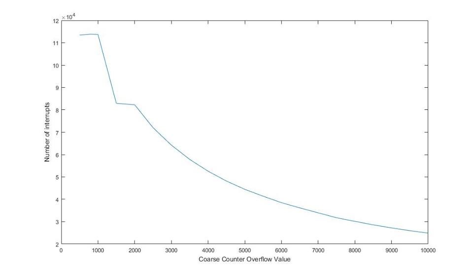
    We performed the experiment to verify the speed of TDC7200:

    - Connect TRIGG to START

    - Do not give STOP signal

    - Configure OVERFLOW register

    - Skip the Readout time

    The graph shows the relationship between the number of interrupts over the value of OVERFLOW COUNTER register. 

    Based on the example result on Page 16 of TDC7200 Manual, TIME1 = 4175 at CLOCK = 8MHz and CALIBRATION_PERIODS = 10 corresponds to 247ns..

    We think that OVERFLOW = 1000 can be interpreted to  STOP at 247 * 1000/4175 = 59ns and OVERFLOW = 8500 is translated to STOP at 500ns. However, the experiment results look different. We could not reach 170K points even though we did not perform the read out. 

    Could you explain this issues?

    Thank you very much.

    --Truong