Other Parts Discussed in Thread: TDC1000, TDC7200, TDC7200EVM
Customer Problem:
- Use TDC1000 to measure drill depths for a “professional” quality drill with the following specifications:
- Min distance 17cm (from transducer)
- Max distance 70cm (from transducer)
- Measurement accuracy ~5mm
- Work even in “hammer drill mode”
- Setup needs to be unaffected by “dust” (sealed transducer)
- Need single transducer solution as cost is an issue.
Since air is so absorptive with respect to ultrasound higher excitation voltages are required. How high, depends on several factors:
- Distance. The farther, the higher voltage required as power drops off exponentially with distance. For this range 30V should work fine.
- Target angle: The further I'm off angle the smaller amplitude echo I'll receive.
- Surface reflectivity: A nice smooth surface will give a better echo than a rough varied one (think flat lumber vs. tree bark).
In a nutshell 1-3 above all relate the SNR of my ultrasound signal path. Changing any of the above will the size of my echo and reduce my measurable distance.
For ease I used the TDC1000_GASEVM as it:
- Is powered from USB
- has up to 30V excitation build in. (which can be bypassed to test lower voltages)
- Can interface to 2 transducers should I really need a short range lower than the ringdown time of a single transducer.
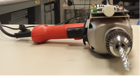
I mounted it on a blank PCB board which I then attached to a hammer drill with velcro straps.
Testing in the lab yielded some promising results:
- I was concerned the “hammer vibrations” would interfere with the transducer so created a test to simulate that by drilling with a fixed depth in “hammer drill” mode.
- The vibrations were not observable
See below:
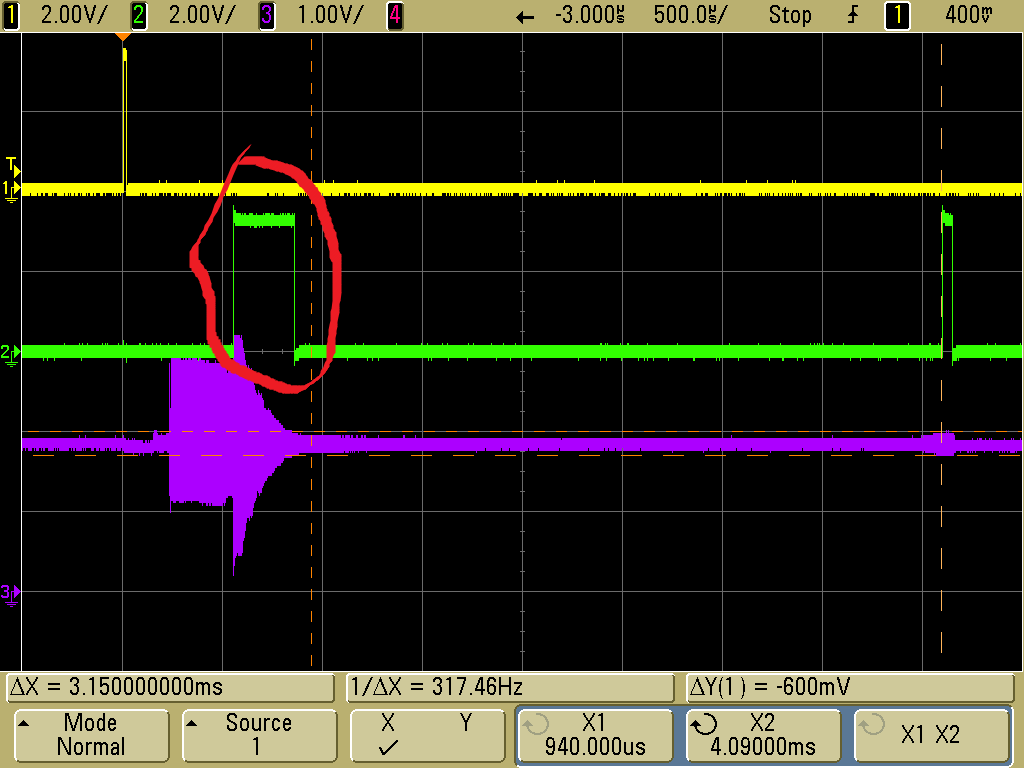
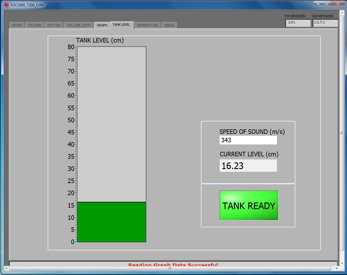
With Drill running and no depth change (no hammer mode)

In air a STD of 3.02us yields [343 m/s*3.02e-6)/2] approximately .5mm
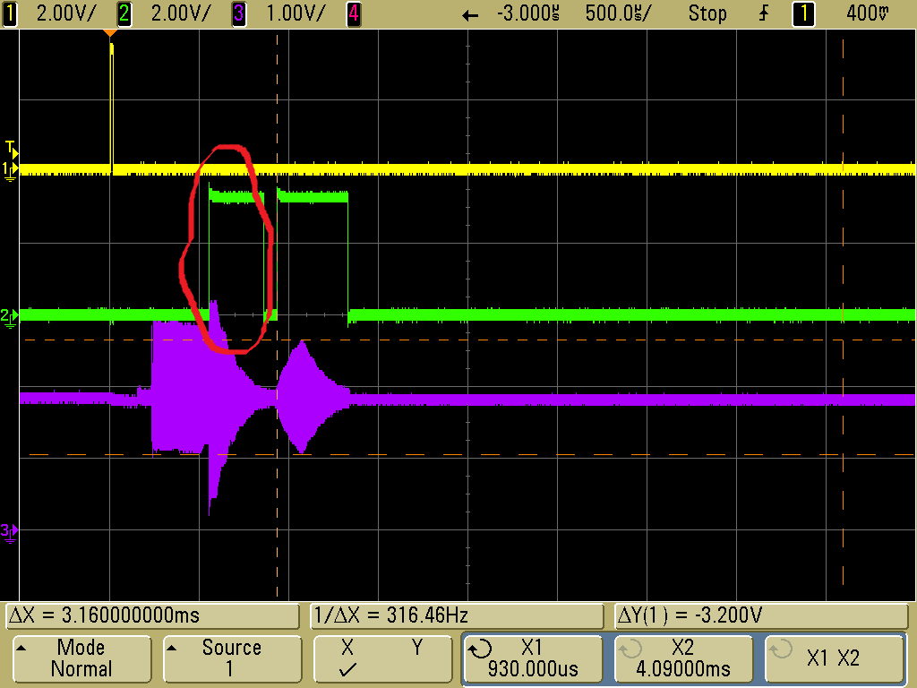
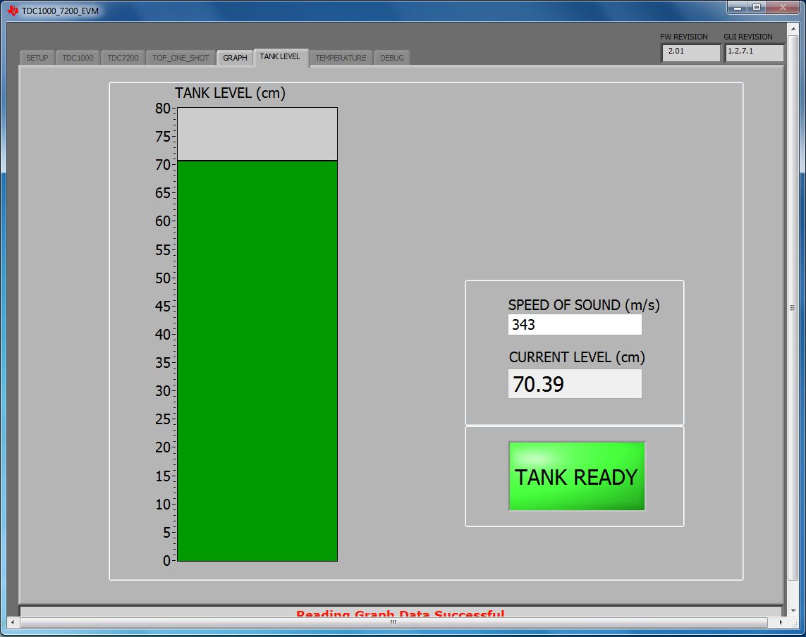
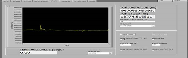
With drill running in Hammer mode(and no depth change)
So drilling with no depth change and no filtering other than averaging yields:
In air a STD of 18.774us yields [343 m/s*18.774e-6)/2] approximately 3.2mm
What EVM/drill combo looked like:
Side view:
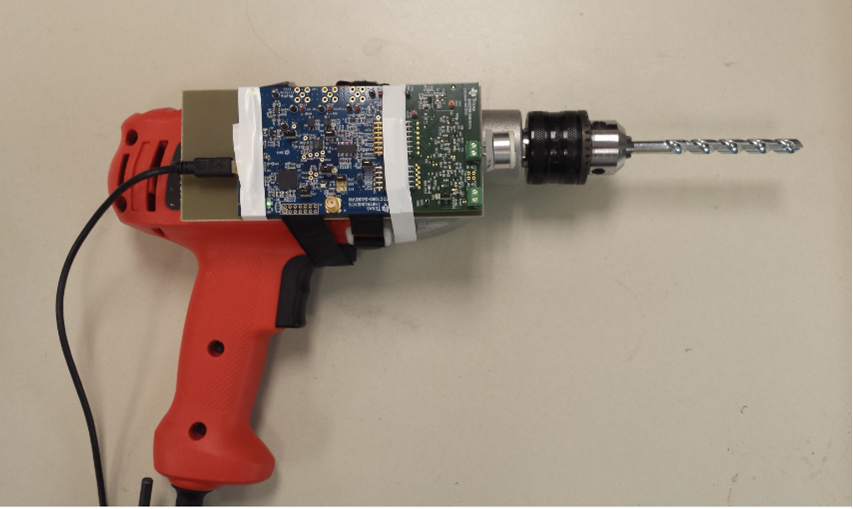
Front View:
During testing (note: metal plate used to make zero depth change)
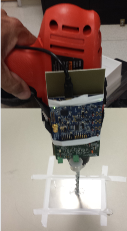
If the drill is not orthogonal to the surface by more than 10 degrees (approx.) no echo is detected (due to the tight beam transducer used).
- Transducer used: Bestartech's 200kHz "sealed" air transducer. A really important feature of this transducer is its tight beam angle which allows it to work so well for this application. The tighter the beam angle the less energy dissipated over a larger area to the longer a distance that can be measured with lower excitation frequencies.
The vendor link: (http://www.bestartech.com/sensors-waterproof-sensors-c-1_21_23-l-en.html)
Arrow’s link: (https://www.arrow.com/en/products/bpu19200ifah11/bestar-technologies)
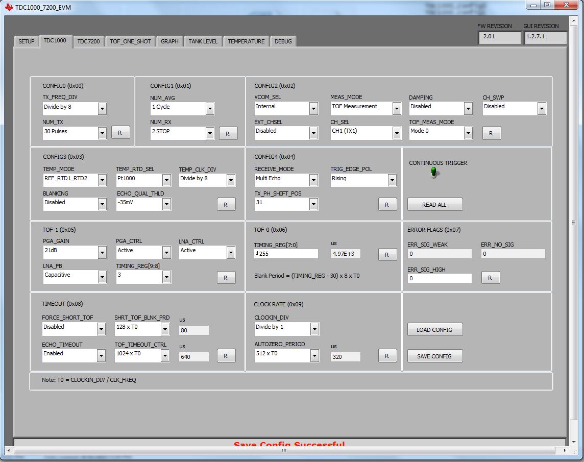
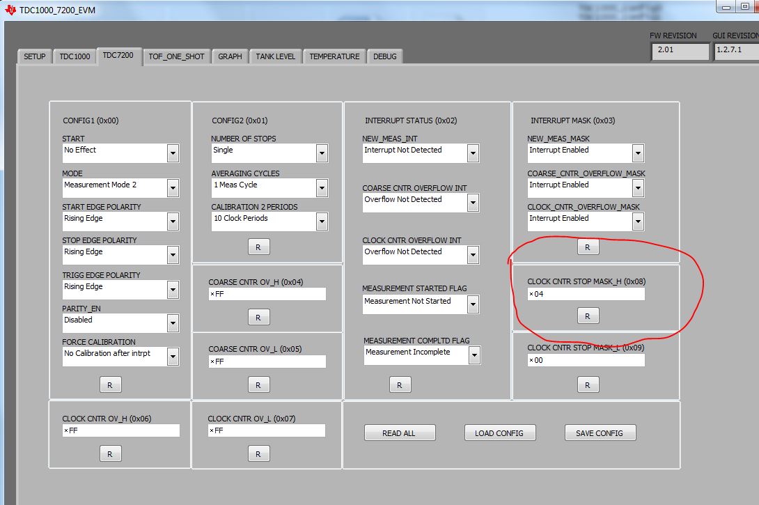
- register files for the above setup are here:
- Also the clock source is CPU_CLK (1.2Mhz) on the board (see TDC1000_GASEVM User's Guide).
Another thing to keep in mind is this setup setup can be used to do level sensing in a container "From the Top" of the container. The issue with that application is that any liquid condensing on the transducer face will severely limit range and will require experimentation.
Also it is ESSENTIAL to read my app note on Sensing Level as it goes over understanding and characterizing transducer ring-down for your system and how to adjust the TDC1000 to compensate for it.