This thread has been locked.

If you have a related question, please click the "Ask a related question" button in the top right corner. The newly created question will be automatically linked to this question.

TDC7200EVM GUI save to file interval setting ( I want to set it less than 100mS --- 20uS = 50ksps)

Other Parts Discussed in Thread: TDC7200EVM, TDC7200, MSP-EXP430F5529LP, MSP430F5529

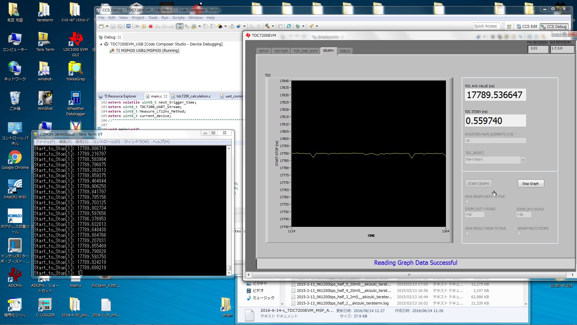
I can save the time span data to file in TDC7200EVM GUI all right. 

But, there is one porblem.  

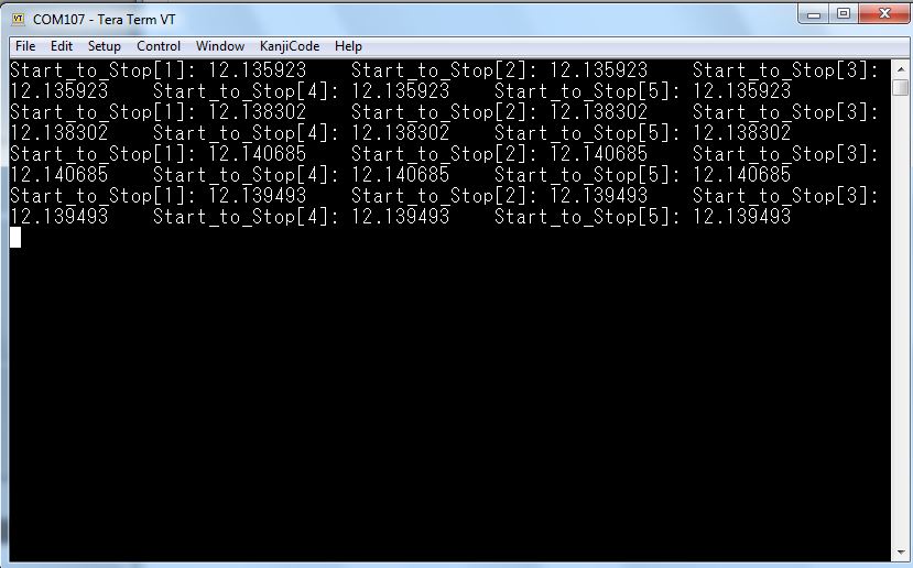
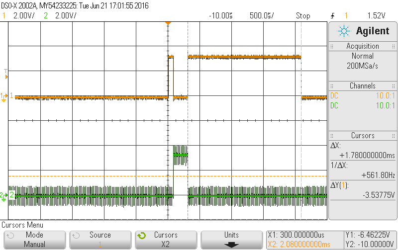
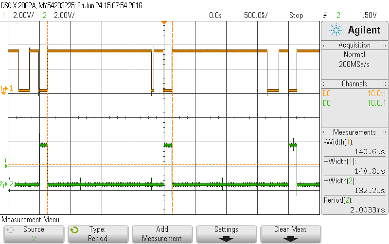
I want to save the time span data (around 17uS) every 20uS. 

I checked the log file and found only 5 data per second = every 200mS. 

I found the setting but the minimum setting is 100mS.  

Would you please show me how to save the time span data every 20uS = 50ksps?

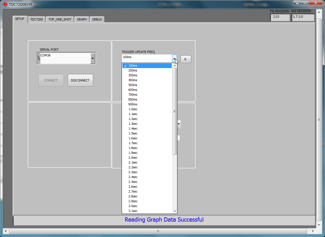
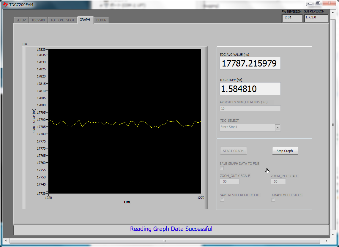
Trigger update freq = 100mS minmum = 10sps max

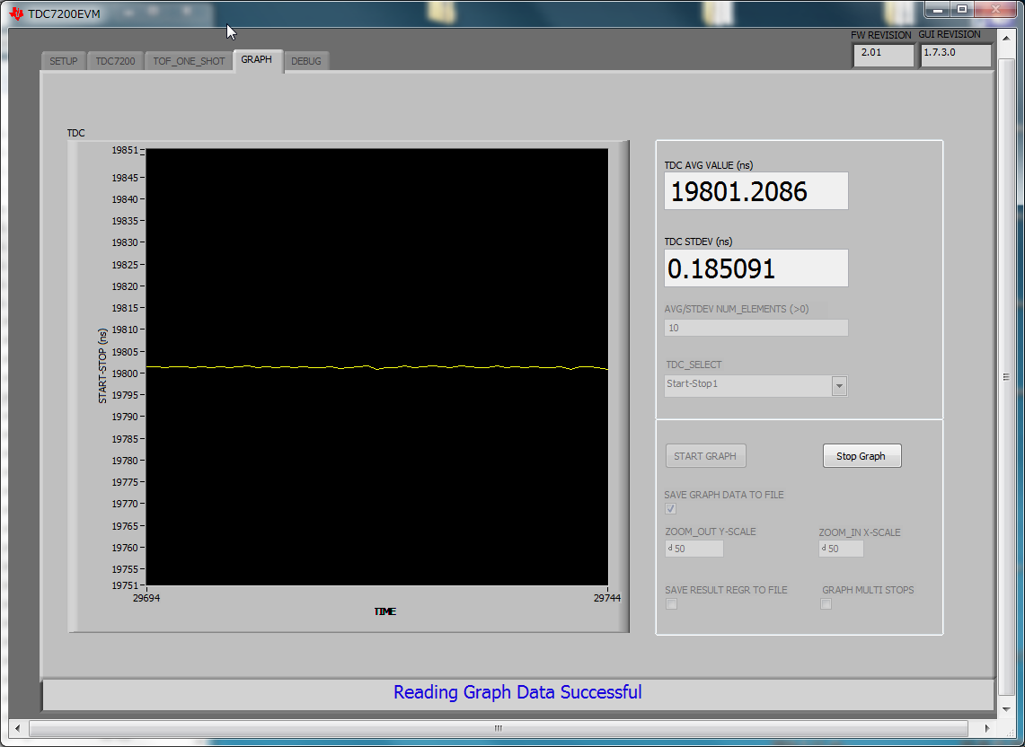
Save graph data to file.

  • Hi Koyo,

    a) As the TDC1000-TDC7200EVM is sending data over USB to the GUI, we cannot support such high sampling rates. The USB latency can be as high as 5-10ms sometimes.
    b) As the time of flight user is measuring can itself be the order of 50-100us (depending on the level or diameter of pipe), we cannot support sampling faster than typical TOF.
    c) If you want highest possible sampling rate for your application, then it is something you have to customize and build it.

    Thanks,
    Vishy
  • Koyo,

    After reading your posting on the inductive sensing forum, I understand why you were asking 50ksps. Here are some inputs:
    a) Make sure you configure the same edge polarity for the start and stop input signals to achieve best accuracy
    b) At present the firmware reads all the 39 bytes of the measurement result registers and sends it over USB to the GUI. These 39 bytes are also sent out on the UART pins.
    c) To achieve 50us sampling, you have to customize the firmware. The EVM firmware source code is part of the GUI install folder and you can find it under C:\Program Files (x86)\Texas Instruments\TDC7200EVM\Firmware. You can find both CCS and IAR project files to build the EVM source code. Instead of sending the results to GUI, you just send buffered results (of only a subset of the registers) over the UART pins to save to a file.

    Thanks,
    Vishy
  • Thank you very much for your help!
    I found the CCS project all right.

    So, I should import the "TDC7200_basic_spi_rw" to CCS and use it as the startup code.

    After download is finished, I can't use the TDC7200EVM GUI.
    I think I should communicate with TDC7200EVM over serial port using terminal software such as Hyper Terminal.

    Would you please the setting (boud rate, etc) and how I can communicate with the TDC7200EVM with the new firmware?
  • I tried 38.4kbps but no data came down from it yet.
    Are there "How to use the "TDC7200_basic_spi_rw" " somewhere?
    I couldn't find it.
    I'll try to read the source code to understand how to communicate with it,
    but I think it will take long time...
  • I imported the "TDC7200_USB" to CCS and push debug button.
    I changed the compile option for printf from minimal to full all right.

    After download is finished, I can use the TDC7200EVM GUI.
    So, this is the source code which communicate with TDC7200EVM GUI.
    TDC7200EVM GUI indicate this is the firmware rev 2.01 all right.

    So, I must add some program to send the time data over the high speed serial I/O.
    Is it possible to set the UART on MSP-EXP430F5529LP to 921.6kbps or higher? How much data I can send over the UART to PC?

    Do you have some sample code I can use as the example?
  • Koyo,
    I looked at the code and here are a few suggestions:
    a) File uart_commn.h: SMCLK_FREQ and UART_BAUDRATE are selected here. Note for UART (and USB communication), SMCLK source is set as the 4MHz XT2 clock.
    b) File uart_commn.c: You have to change UCAxMCTL register (line 63) corresponding to selected baud rate. Refer MSP430F5529 UG slau208 table 36-4. You can go maximum 230400 and use UCAxMCTL = (UCBRF_0|UCBRS_3);
    c) File tdc720x_calculation.c: function print_start2stopn has all the 39 bytes of registers printing commented out already and printing only Start_to_Stop array values. Change line 86 "MAX_STOPS" to 1 so only 1 stop value is printed . This reduces communication on the port to only needed values.
    d) You need to use FTDI UART to USB cable to see the data with a "Tera Term" kind of terminal program.

    Thanks,
    Vishy
  • One correction: I forgot you are using the launchpad in which case the UART back channel is used for communication. So you don't need FTDI cable. Thanks,
  • There are more changes to do to achieve 20us trigger
    a) File timer_queue.c: Comment out line 115 "TA1EX0 = TAIDEX_7; // further divide by 8" so timer count is finer to accommodate 20us
    b) File timer_queue.h: we define here different timer intervals for 4MHz clock with only divide 4 (not 32): 10ms corresponds to 10000 timer count. So 20us will correspond to 20. Add "#define INTERVAL_20us 20".
    c) File timer_queue.c: Change line 109 "TA1CCR0 = INTERVAL_100ms;" to "TA1CCR0 = INTERVAL_20us";
    d) File host_interface.c: Comment out line 233 "timer_trigger_freq = word_data;" This prevents GUI from setting timer trigger freq

    Thanks,
    Vishy

  • Thank you very much for the information!

    So, I must edit several files in the TDC7200EVM USB project!

    Well, there are a lot of lines I have to change.  main.c tdc7200_calculation.c timer_queue.c uart_commn.c  ...

    As I don't understand the original source code file, I might change the wrong lines which I shouldn't touch.  

    If possivle, would you please make me the souce code to do the 20uS measurement?

    It would be very kind of you if you give me the tested source code to measure the time (around 17uS) every 20uS and send it to serial terminal at 1Mbps.  

    I know I ask you too much.  

    1Mbps * 20uS = 20 bit = 2 byte = I can send 16 bit binary value every 20uS over 1Mbps serial interface.

    It'll take me more than 1 week to make the program I need, if I do it myself. 

  • Please first check if you can get software help from your local TI FAE. Thanks, Vishy
  • I decided to follow your advice.  

    I use CCS to debug TDC7200EVM_USB.  

    To check the UART,  I checked the COM port.

    I opened the MSP Application UART1(COM34) using TeraTerm.  

    I set the baudrate at 38.4kbps. 

    I started the graph. 

    I checked the TDC7200 Uart Stream.

    But, nothing is coming to TeraTerm window. 

    What should I do?

  • Your steps look correct. Please make sure your tera term settings are fine. You can also check if data is coming from TOF_ONE_SHOT tab. If for any reason you disconnect and reconnect the GUI, you  have to unselect and select the "TDC7200 Uart Stream" option again because the firmware loses the setting after a disconnect /reconnect.

    I tried it now. See some screen shots below to help. Thanks.

  • As a matter of fact, I tried it on CodeComposerStudio Debugger yesterday.
    I got no data on TeraTerm yesterday.
    (CCS Debugger seems to Use the back channel UART somehow, I guess.)
    Today, I tried without CCS Debugger. Just plug in the TDC7200EVM board and started the GUI and TeraTerm.
    I got data stream on the TeraTerm window all right.
    Thank you very much for your help!
    I think now I can proceed with changing the parameters you mentioned.
  • I use CCS Debugger to run TDC7200EVM_USB now.  

    I don't know why, but today, TeraTerm shows the serial data all right.

    So, CCS Debugger was not the cause of the problem.

  • To enable 921.6kbps UART, I decided to changed the clock frequency.  

    (1) main.c    void Init_Clock(void)

    // UCSCTL2 = FLLD_0 + 731; // Set DCO Multiplier(762/498) for 25MHz/16MHz

    //DCO=32768*732=23.986176MHz

    UCSCTL2 = FLLD_0 + 674; // Set DCO Multiplier(675) for 22.1184MHz kegasa DCO=32768*675

    // kegasa comment 3^3*5^2=675    2^15*3^3*5^2 = 22.1184MHz

    // UCSCTL4 = SELA__XT1CLK + SELS__XT2CLK + SELM__DCOCLKDIV; // SMCLK=4MHz MCLK=24MHz
    UCSCTL4 = SELA__XT1CLK + SELS__DCOCLKDIV + SELM__DCOCLKDIV;

    // SMCLK= 22.1184MHz   MCLK=24MHz

    (2) uart_commn.c

    void InitUART(void)

    // UCAxBR = UART_BAUDRATE_REG; // defines baudrate

    UCAxBR = 1; // kegasa defines baudrate kegasa UCOS16 = 1

    // UCAxMCTL = (UCBRF_0|UCBRS_3); // 38400 baudrate selection @ 4MHz

     UCAxMCTL =  (UCBRF_8|UCBRS_0|UCOS16);            //  kegasa  921.6kbps  baudrate selection @ 22.1184MHz  over sampling mode

    Strangely, Baudrate is higher than 1Msps now.  Not 921.6kbps I designed.  

    And TDC7200EVM GUI graph dosen't show any line. 

    I go back to the original file, and it is working all right.  

    What should I do?

    I also tried 16*921.6kHz = 14.7456 MHz clock. 

    Baudrate setting is 921.6kbps all right. ( I checkd the TxD using osiclloscope )

    But, I can't get any data using TeraTerm.  

    And on TDC7200EVM GUI the graph dosen't show any line. 

    What is wrong?

  • I think there is maximum speed for "The backchannel UART" = "MSP Application UART1".
    I tried 55.6kbps all right.
    I also tried 115.2kbps all right. TeraTerm window shows the correct data.
    But, whenI tried 320.4kbps strange characters are appeared in TeraTerm window.
    I checked the TxD port with oscilloscope and found the serial signal is all right.

    Would you please check what is the maximum baudrate allowed on "The backchannel UART" = "MSP Application UART1" please?
  • I think I tried all the suggestions you had given me.
    Now I can get the data at 10mS interval all right. ( 100sps )
    There are two strange points.

    (a) Maximum baudrate is 115200bps.
    I tried 230400bps.
    Although the signal at the TxD port looks good, Teraterm show strange characters.
    Maybe I hit the back channel interface's speed limit.

    (b) Interval is twice of the setting.
    When I set 10mS, data is coming at 20mS interval.
    When I set 5mS, data is coming at 10mS interval.
    When I set less than 2.5mS, data is coming at 6.8mS interval.

    Maybe I hit the 6.8mS interval time limit.
    f = 147 Hz = 147sps is the best.

    I want to accomplish my goal of 20uS interval ( f = 50kHz ).
    But maybe this is the limit of TDC7200EVM.
    Maybe I should design new board with faster USB serial adapter.
    Maybe I should use stronger MPU.

    If you have more suggestion, please give them to me!


    Below are the programs I changed and the Teraterm logs I got.


    (1) uart_commn.h

    #define ACLK_FREQ 32768 // ACLK frequency of MCU, in Hz
    #define SMCLK_FREQ 4000000 // SMCLK frequency of MCU, in Hz kegasa original setting
    #define USCI_A_MODULE 1 // Select which USCI_A module to use [0-1]
    // #define UART_BAUDRATE 38400 //Specify baudrate all right
    // #define UART_BAUDRATE 57600 //Specify baudrate all right
    #define UART_BAUDRATE 115200 //Specify baudrate 115.2kbps kegasa all right
    // #define UART_BAUDRATE 230400 //Specify baudrate 230.4kbps kegasa Dosen't work
    #define UART_BAUDRATE_REG (unsigned short)(SMCLK_FREQ/UART_BAUDRATE)


    (2) uart_commn.c

    UCAxBR = UART_BAUDRATE_REG; // defines baudrate

    // UCAxMCTL = (UCBRF_0|UCBRS_3); // 38400 baudrate selection @ 4MHz all right
    // UCAxMCTL = (UCBRF_0|UCBRS_4); // 57600 baudrate selection @ 4MHz all right
    UCAxMCTL = (UCBRF_0|UCBRS_6); // 115200 baudrate selection @ 4MHz kegasa all right
    // UCAxMCTL = (UCBRF_0|UCBRS_3); // 230400 baurate selection @ 4MHz kegasa Dosen't work


    (3) timer_queue.h

    // #define INTERVAL_100ms 12500 // original (there is 1/8)
    #define INTERVAL_100ms 100000 // 12500 *8 kegasa
    #define INTERVAL_10ms 10000 // 1250 *8 kegasa result=20mS
    #define INTERVAL_5ms 5000 // 625 *8 kegasa result=10mS
    #define INTERVAL_2500us 2500 // kegasa result=6.8mS
    #define INTERVAL_1ms 1000 // kegasa result=6.8mS


    (4) timer_queue.c

    void timer1_A0_init(void)
    {
    // TA1CCR0 = INTERVAL_100ms; //
    // TA1CCR0 = INTERVAL_10ms; // kegasa speed up version result=20mS
    // TA1CCR0 = INTERVAL_5ms; // kegasa speed up version result=10mS
    // TA1CCR0 = INTERVAL_2500us; // kegasa speed up version result=6.8mS
    TA1CCR0 = INTERVAL_1ms; // kegasa speed up version result=6.8mS

    // enable timer interrupt
    TA1CCTL0 |= CCIE; // TA1CCR0 interrupt enabled
    // Note: TACLR clears both counter and clock divider: setup divider later
    TA1CTL |= TACLR;
    TA1CTL = TASSEL_2 + MC_1 + ID_2; // SMCLK (4MHz), clear TAR, conts mode, divide by 4, no overflow intrpt TAIE
    // TA1EX0 = TAIDEX_7; // further divide by 8 kegasa comment out to speed up


    (5) tdc7200_calculation.c

    void print_start2stopn(void)
    {
    uint8_t i;

    // ...

    // for (i=0;i<MAX_STOPS;i++) // kegasa original
    for (i=0;i<1;i++)
    {
    // sprintf((char *)outString, "Start_to_Stop[%d]: %4.6f ", i+1, start2stop[i]); // original
    sprintf((char *)outString, "%4.3f", start2stop[i]); // short text kegasa
    putsUART((unsigned char *)outString,strlen((char *)outString));
    }
    sprintf((char *)outString, " \r\n");
    putsUART((unsigned char *)outString,strlen((char *)outString));
    }


    (6) host_interface.c

    // timer_trigger_freq = word_data; // frequency is fixed now kegasa


    (7) 2016-6-17-a_debug_115400bps_10mS_teraterm.log

    0001
    0002 [Fri Jun 17 11:11:37.977 2016] Hello World
    0003 [Fri Jun 17 11:11:42.053 2016] 17790.779
    0004 [Fri Jun 17 11:11:42.053 2016] 17788.057
    ...
    0503 [Fri Jun 17 11:11:52.055 2016] 17789.205

    f = (52.055-42.053)*1000/(503-3)=20.0ms


    (8) 2016-6-17-b_debug_115400bps_5mS_teraterm.log

    0002 [Fri Jun 17 11:19:09.312 2016] Hello World
    0003 [Fri Jun 17 11:19:12.687 2016] 17790.990
    ...
    1003 [Fri Jun 17 11:19:22.659 2016] 17793.166

    f = (22.659-12.687)*1000/(1003-3)=9.972ms


    (9) 2016-6-17-c_debug_115400bps_2500uS_teraterm.log

    0003 [Fri Jun 17 11:24:40.721 2016] 17788.744
    ...
    1003 [Fri Jun 17 11:24:47.547 2016] 17792.789

    f = (47.547-40.721)*1000/(1003-3)=6.826ms


    (10) 2016-6-17-d_debug_115400bps_1mS_teraterm.log

    0003 [Fri Jun 17 11:30:07.200 2016] 17792.244
    ...
    1003 [Fri Jun 17 11:30:14.013 2016] 17791.504

    f = (14.013-07.200)*1000/(1003-3)=6.813ms
  • I reviewed your posts:
    a) You can't change SMCLK to DCO for higher speed. DCO is not accurate and therefore UART would not function. That's why you didn't see anything coming out. So it's important you retain XT2 as the source of SMCLK.
    b) If you want higher baud rate change 4MHz crystal to say 16 or 24MHz. Then you also have to change a USB header file (don't remember the exact file but I can tell you later if you want) that say XT2 frequency is not 4MHz but 16 or 24MHz. That would ensure USB continues to work as well as you have higher UART baud rate. Going to higher clock freq would also help on the timer interval setting.
    c) You cannot use the tera term time stamp to derive your baud rate (I don't think they are accurate). If you want to check that, then toggle a GPIO pin from inside the timer interrupt routine and then check on the scope the frequency on the pin.
    Thanks,
    Vishy
  • I tried your idea to measure the time using GPIO. 

    In main.c, I add these lines below.

    P4DIR |= BIT1; // P4.1 = output kegasa
    P4OUT |= BIT1; // P4.1 = output high kegasa
    P8DIR |= BIT1; // P8.1 = output kegasa
    P8OUT |= BIT1; // P8.1 = output high kegasa

    In tdc7200_calculation.c, I changed the tdc7200_calc() by adding some lines.


    void tdc7200_calc(uint8_t *buf, uint8_t dev)
    {
    P4OUT &= ~BIT1 ; // P4.1 = low kegasa
    P8OUT &= ~BIT1 ; // P8.1 = low kegasa
    P4OUT |= BIT1 ; // P4.1 = high kegasa
    tdc7200_build_mreg(buf);
    P4OUT &= ~BIT1 ; // P4.1 = low kegasa
    P8OUT |= BIT1 ; // P8.1 = high kegasa
    tdc7200_start2stopn(dev);
    P8OUT &= ~BIT1 ; // P8.1 = low kegasa
    P4OUT |= BIT1 ; // P4.1 = high kegasa
    print_start2stopn();
    P4OUT &= ~BIT1 ; // P4.1 = low kegasa
    }

    tdc7200_calc is running every 20mS.  (setting is 10mS)

    It took 78uS to read the all the measure register = 39 byte.  

    I must omit some of the register reading process to do it in 20uS. 

    It took 228uS to calculate time. 

    I need more CPU power to calculate the time spans in 20uS,  

    It took 1.78mS to print out the data to UART.  

    I need faster UART to send them in 20uS.

    Thank you very much for your help. 

    Please suggest me what I shoud do next. 

    Should I use MSP432 series or faster one?

  • Here are some suggestions
    a) You can get faster UART trasmit by replacing XT2 with a higher MHz crystal. In that case make sure the variable USB_XT_FREQ_VALUE in descriptor.h is updated to the new value.
    b) Since float operations are time consuming, just read and send only the needed registers over UART.
    c) You can initialize all the registers in firmware, and comment the USB initialization. Set the "graph_tof_state" variable and "TDC720x_UART_Stream" variable to 1 in main.c before the while loop. This can save you time as well.
    d) After all the debugging, use the compile optimization options to compile for speed.

    Yes, MSP432 would help as it can run faster and it's also 32-bit CPU.

    Thanks,
    Vishy

  • Thank you very much for your advice!

    I change some of the source code following your advice. 

    Now, I can get data at 500sps (2mS).  More than 3 times faster than the last result (6.8mS)!

    I'll tune up some more software this week, and try MSP432 next month. 

    I started @100mS, Now @2mS, 50 times faster!

    My goal is @20uS, 100 times faster to go!

    Below are the part of the souce code I changed.  


    (1) main.c

    TI_TDC7200_reg_init();
    TI_TDC7200_SPIByteWriteReg(TI_TDC7200_CONFIG1_REG, 0x03, current_device); // Default Mode 2 kegasa measure start

    while (1)
    {
    // __bis_SR_register(LPM0_bits + GIE); // Enter LPM0, enable interrupts
    __no_operation(); // For debugger
    // USBCommunicationTask(); // comment kegasa
    if (next_trigger_time)
    {
    next_trigger_time = 0;
    // tdc_trigger_measure(); // comment kegasa
    wait_on_intb_pin(TI_TDC7200_INTB1_PIN); // kegasa
    P8OUT |= BIT1 ; // P8.1 = high kegasa
    TI_TDC7200_SPIAllReadReg(mbuf, TDC7200_DEV1); // kegasa read all TDC7200 measure registers
    __no_operation(); // For debugger
    TI_TDC7200_SPIByteWriteReg(TI_TDC7200_CONFIG1_REG, 0x03, current_device); // Default Mode 2 kegasa measure start
    __no_operation(); // For debugger
    P8OUT &= ~BIT1 ; // P8.1 = low kegasa
    tdc7200_calc(mbuf, TDC7200_DEV1); // kegasa
    __no_operation(); // For debugger

    }
    __no_operation(); // For debugger

    }
    }

    (2) tdc7200_calculation.c

    void tdc7200_calc(uint8_t *buf, uint8_t dev)
    {
    P4OUT &= ~BIT1 ; // P4.1 = low kegasa
    P4OUT |= BIT1 ; // P4.1 = high kegasa
    tdc7200_build_mreg(buf);
    tdc7200_start2stopn(dev);
    P4OUT &= ~BIT1 ; // P4.1 = low kegasa
    P8OUT |= BIT1 ; // P8.1 = high kegasa
    print_start2stopn();
    P8OUT &= ~BIT1 ; // P8.1 = low kegasa
    }


    void print_start2stopn(void)
    {
    uint8_t i;
    // for (i=0;i<MAX_STOPS;i++) // kegasa original suggestion by Vishy
    for (i=0;i<1;i++)
    {
    // sprintf((char *)outString, "Start_to_Stop[%d]: %4.6f ", i+1, start2stop[i]); // original kegasa
    sprintf((char *)outString, "%4.2f", start2stop[i]); // short text kegasa
    putsUART((unsigned char *)outString,strlen((char *)outString));
    }
    sprintf((char *)outString, " \r\n");
    putsUART((unsigned char *)outString,strlen((char *)outString));
    }


    void tdc7200_start2stopn(uint8_t dev)
    {
    uint8_t n;

    tdc7200_normlsb(dev);
    // do for 5 stops
    // for(n=0; n < MAX_STOPS; n++)
    for(n=0; n < 1; n++) // calculate only 1 time kegasa
    start2stop[n] = norm_lsb * (meas_result_regrs[0] - meas_result_regrs[2*(n+1)]) +
    tdc_clk_period * meas_result_regrs[2*(n+1)-1];

    }

    void tdc7200_build_mreg(uint8_t *buf)
    {
    uint8_t i;
    for(i=0; i < 2; i++) // Time1 and Clk_count1 only kegasa
    {
    meas_result_regrs[i] = (((uint32_t) buf[3*i]) << 16) +
    (((uint32_t) buf[(3*i)+1]) << 8) +
    (((uint32_t) buf[(3*i)+2]));
    }
    for(i=10; i < MEAS_RESULT_REG_NUM; i++) // Time6 and Calibration1 and Calibration2 kegasa
    {
    meas_result_regrs[i] = (((uint32_t) buf[3*i]) << 16) +
    (((uint32_t) buf[(3*i)+1]) << 8) +
    (((uint32_t) buf[(3*i)+2]));
    }
    }

    (3) TI_MSP430_spi_USCIB0_5xx.c

    void TI_TDC7200_SPISetup(void)
    {
    TI_TDC7200_CSB1_PxOUT |= TI_TDC7200_CSB1_PIN;
    TI_TDC7200_CSB1_PxDIR |= TI_TDC7200_CSB1_PIN; // /CS disable

    TI_TDC7200_CSB2_PxOUT |= TI_TDC7200_CSB2_PIN;
    TI_TDC7200_CSB2_PxDIR |= TI_TDC7200_CSB2_PIN;

    UCB0CTL1 |= UCSWRST; // **Disable USCI state machine**
    UCB0CTL0 |= UCMST+UCMSB+UCCKPH+UCSYNC; // 3-pin, 8-bit SPI master
    UCB0CTL1 |= UCSSEL_2; // SMCLK
    // vishy
    // UCB0BR0 = 0x02; // UCLK/2 (should be 2MHz for 4MHz SMCLK)
    UCB0BR0 = 0x01; // kegasa TDC7200 can accept 20MHz clock so 4MHz is low enough
    UCB0BR1 = 0;

    TI_TDC7200_SPI_USCIB0_PxSEL1 |= TI_TDC7200_SPI_USCIB0_SIMO
    | TI_TDC7200_SPI_USCIB0_SOMI;
    TI_TDC7200_SPI_USCIB0_PxSEL2 |= TI_TDC7200_SPI_USCIB0_UCLK;
    // SPI option select
    TI_TDC7200_SPI_USCIB0_PxDIR1 |= TI_TDC7200_SPI_USCIB0_SIMO;
    TI_TDC7200_SPI_USCIB0_PxDIR2 |= TI_TDC7200_SPI_USCIB0_UCLK;
    // SPI TXD out direction

    UCB0CTL1 &= ~UCSWRST; // **Initialize USCI state machine**
    }


    void TI_TDC7200_SPIAllReadReg(uint8_t *buffer, uint8_t dev) // kegasa read all 13*3byte = 13 * 24bit register value.
    {

    uint8_t i, inst;

    P8OUT |= BIT1 ; // P8.1 = high kegasa

    if (dev == TDC7200_DEV1)
    TI_TDC7200_CSB1_PxOUT &= ~TI_TDC7200_CSB1_PIN; // /CS enable
    else
    TI_TDC7200_CSB2_PxOUT &= ~TI_TDC7200_CSB2_PIN;

    // read mode and auto_inc on
    inst = 0x90;

    while (!(UCB0IFG&UCTXIFG)); // Wait for TXBUF ready
    UCB0TXBUF = inst; // Send register address


    for(i=0; i<TDC7200_ALL_DATA_SIZE; i++)
    {
    while (!(UCB0IFG&UCTXIFG)); // Wait for TXBUF ready
    UCB0TXBUF = 0; // Dummy write so we can read data


    while (UCB0STAT & UCBUSY); // Wait for TX complete
    *(buffer+i) = UCB0RXBUF; // Read register data
    }

    if (dev == TDC7200_DEV1)
    TI_TDC7200_CSB1_PxOUT |= TI_TDC7200_CSB1_PIN; // /CS disable
    else
    TI_TDC7200_CSB2_PxOUT |= TI_TDC7200_CSB2_PIN;

    P8OUT &= ~BIT1 ; // P8.1 = low kegasa
    }