This thread has been locked.

If you have a related question, please click the "Ask a related question" button in the top right corner. The newly created question will be automatically linked to this question.

Starterware/AFE5809EVM: AFE5809EVM initialization using SPI connection

Part Number: AFE5809EVM
Other Parts Discussed in Thread: AFE5809

Tool/software: Starterware

Dear Friends,

I've been struggling to initialize AFE5809EVM using SPI module of the OMAP L138 LCDK. Previously, I have successfully initialized AFE5809EVM  and TSW1400EVM using AFE5809EVM GUI. I decided to create a comprehensive reference of how to initialize AFE5809EVM in here. Hopefully we solve the issue, and this thread would be beneficial to future users.

As suggested in this thread (e2e.ti.com/.../576643), I have:

  1. First, initiated the AFE5809EVM using the AFE5809EVM GUI
  2. Second, I have disconnected FB17 on AFE EVM board (at this stage the AFE5809EVM is successfully initialized by the GUI. Now we disconnect the FB17, so we can start SPI connection using P14 pins.)
  3. Third, I have connected the SPI pins of OMAP L138 EVM to the P14 of AFE5809EVM.
  4. I test if I can properly communicate through SPI or not. To do this, I simply enable read out (by setting register 00 = (value) 0x0002 ) and then reading register 04.
  5. When I do this test, I cannot see any change on TP 12.

Please verify the correctness of the following statements:

  • The SPI of AFE5809EVM uses High-polarity and out of phase clock (Figure 83. SPI Timing of afe5809). In code, we need this information in this line:

    SPIConfigClkFormat(SOC_SPI_1_REGS, (SPI_CLK_POL_HIGH | SPI_CLK_OUTOFPHASE),
    dataFormat);

  • In order to just initialize AFE5809, I just need to connect SCLK, SDATA, GND, and SEN pins of P14 to the proper SPI pins of OMAP L138LCDK. (I don't need to connect any of these pins: PDN_GLOBAL, PDN_VCA, SPI_DIG_EN, or any other pins on the P14 of AFE5809EVM)

  • This code is a modified version of Starterware SPI example. Is the code ok? 
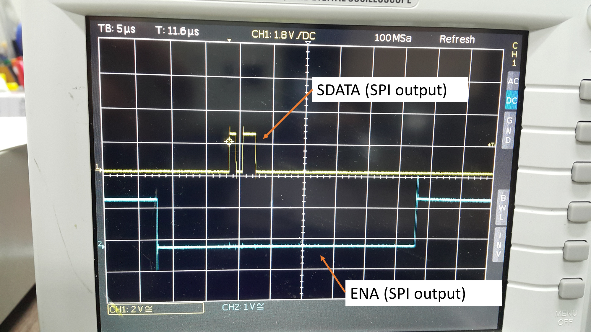
  • Please verify that the SPI signals shown on the oscilloscope below are OK.

Thank you so much for your time. I really appreciate it :)

my code:

/**
 * \file spi.c
 *
 * \brief  This is a sample application file which invokes some APIs
 *         from the SPI device abstraction layer to perform configuration,
 *         transmission and reception operations.
 */

/*
 * Copyright (C) 2012 Texas Instruments Incorporated - http://www.ti.com/
 *
 *  Redistribution and use in source and binary forms, with or without
 *  modification, are permitted provided that the following conditions
 *  are met:
 *
 *    Redistributions of source code must retain the above copyright
 *    notice, this list of conditions and the following disclaimer.
 *
 *    Redistributions in binary form must reproduce the above copyright
 *    notice, this list of conditions and the following disclaimer in the
 *    documentation and/or other materials provided with the
 *    distribution.
 *
 *    Neither the name of Texas Instruments Incorporated nor the names of
 *    its contributors may be used to endorse or promote products derived
 *    from this software without specific prior written permission.
 *
 *  THIS SOFTWARE IS PROVIDED BY THE COPYRIGHT HOLDERS AND CONTRIBUTORS
 *  "AS IS" AND ANY EXPRESS OR IMPLIED WARRANTIES, INCLUDING, BUT NOT
 *  LIMITED TO, THE IMPLIED WARRANTIES OF MERCHANTABILITY AND FITNESS FOR
 *  A PARTICULAR PURPOSE ARE DISCLAIMED. IN NO EVENT SHALL THE COPYRIGHT
 *  OWNER OR CONTRIBUTORS BE LIABLE FOR ANY DIRECT, INDIRECT, INCIDENTAL,
 *  SPECIAL, EXEMPLARY, OR CONSEQUENTIAL DAMAGES (INCLUDING, BUT NOT
 *  LIMITED TO, PROCUREMENT OF SUBSTITUTE GOODS OR SERVICES; LOSS OF USE,
 *  DATA, OR PROFITS; OR BUSINESS INTERRUPTION) HOWEVER CAUSED AND ON ANY
 *  THEORY OF LIABILITY, WHETHER IN CONTRACT, STRICT LIABILITY, OR TORT
 *  (INCLUDING NEGLIGENCE OR OTHERWISE) ARISING IN ANY WAY OUT OF THE USE
 *  OF THIS SOFTWARE, EVEN IF ADVISED OF THE POSSIBILITY OF SUCH DAMAGE.
 */

#include <string.h>
#include "soc_OMAPL138.h"
#include "hw_psc_OMAPL138.h"
#include "lcdkOMAPL138.h"
#include "uart.h"
#include "spi.h"
#include "psc.h"
#include "interrupt.h"
#include "uartStdio.h"

/******************************************************************************
 **                      INTERNAL MACRO DEFINITIONS
 *******************************************************************************/
/* value to configure SMIO,SOMI,CLK and CS pin as functional pin */
#define SIMO_SOMI_CLK_CS        0x00000E01
#define CHAR_LENGTH             0x8

/******************************************************************************
 **                      INTERNAL FUNCTION PROTOTYPES
 *******************************************************************************/
static void SPIConfigDataFmtReg(unsigned int dataFormat);
static void SpiTransfer(void);
static void SetUpInt(void);
static void SetUpSPI(void);
static void GetStatusCommand(void);
static void SendCommand(void);
void SPIIsr(void);

/******************************************************************************
 **                      INTERNAL VARIABLE DEFINITIONS
 *******************************************************************************/
volatile unsigned int flag = 1;
unsigned int tx_len;
unsigned int rx_len;
unsigned char vrf_data[260];
unsigned char tx_data[260];
volatile unsigned char rx_data[260];
unsigned char *p_tx;
volatile unsigned char *p_rx;
volatile unsigned char StatusResponseMessage[16];

/******************************************************************************
 **                      INTERNAL FUNCTION DEFINITIONS
 *******************************************************************************/
int main(void)
{
    /* Waking up the SPI1 instance. */
    PSCModuleControl(SOC_PSC_1_REGS, HW_PSC_SPI1, PSC_POWERDOMAIN_ALWAYS_ON,
    PSC_MDCTL_NEXT_ENABLE);

    /* Initializing the UART instance for serial communication. */
//    UARTStdioInit();
    /* Performing the Pin Multiplexing for SPI1. */
    SPIPinMuxSetup(1);

    /* 
     ** Using the Chip Select(CS) 0 pin of SPI1 to communicate with the Fingerprint Sensor.
     */
    SPI1CSPinMuxSetup(0);

    /* Enable use of SPI1 interrupts. */
    SetUpInt();

    /* Configuring and enabling the SPI1 instance. */
    SetUpSPI();

    while (1)
    {
        SendCommand();
        printf("sent");

    }

}

static void SendCommand(void)
{
    // Issue Command enable read out of TP12
    tx_data[0] = 0x00;
    tx_data[0] = 0x00;
    tx_data[0] = 0x02;

    tx_len = 3;
    rx_len = 3;

    SPIDat1Config(SOC_SPI_1_REGS, (SPI_CSHOLD | SPI_DATA_FORMAT0), 0x01);
    SpiTransfer();

    int i = 0;
    while (i < 10000)
    {
        i++;
    }

    // Issue Command read register 04
    tx_data[0] = 0x04;
    tx_data[0] = 0x00;
    tx_data[0] = 0x18;

    tx_len = 3;
    rx_len = 3;

    SPIDat1Config(SOC_SPI_1_REGS, (SPI_CSHOLD | SPI_DATA_FORMAT0), 0x01);
    SpiTransfer();

}

/*
 ** Configures ARM interrupt controller to generate SPI interrupt
 **
 */
static void SetUpInt(void)
{
    // Setup the ARM or DSP interrupt controller

#ifdef _TMS320C6X
    // Initialize the DSP interrupt controller
    IntDSPINTCInit();

    // Register the ISR in the vector table
    IntRegister(C674X_MASK_INT4, SPIIsr);

    // Map system interrupt to the DSP maskable interrupt
    IntEventMap(C674X_MASK_INT4, SYS_INT_SPI1_INT);

    // Enable the DSP maskable interrupt
    IntEnable(C674X_MASK_INT4);

    // Enable DSP interrupts globally
    IntGlobalEnable();
#else
    /* Initialize the ARM Interrupt Controller.*/
    IntAINTCInit();

    /* Register the ISR in the Interrupt Vector Table.*/
    IntRegister(SYS_INT_SPINT1, SPIIsr);

    /* Set the channnel number 2 of AINTC for system interrupt 56.
     * Channel 2 is mapped to IRQ interrupt of ARM9.
     */
    IntChannelSet(SYS_INT_SPINT1, 2);

    /* Enable the System Interrupts for AINTC.*/
    IntSystemEnable(SYS_INT_SPINT1);

    /* Enable IRQ in CPSR.*/
    IntMasterIRQEnable();

    /* Enable the interrupts in GER of AINTC.*/
    IntGlobalEnable();

    /* Enable the interrupts in HIER of AINTC.*/
    IntIRQEnable();
#endif
}

/*
 ** Configures SPI Controller
 **
 */
static void SetUpSPI(void)
{
    unsigned char cs = 0x01; // warning: on change, also change 0x01 in SpiTransfer
    unsigned char dcs = 0x01;
    unsigned int val = SIMO_SOMI_CLK_CS;
    SPIReset(SOC_SPI_1_REGS);

    SPIOutOfReset(SOC_SPI_1_REGS);

    SPIModeConfigure(SOC_SPI_1_REGS, SPI_MASTER_MODE);

    //SPIClkConfigure(SOC_SPI_1_REGS, 150000000, 20000000, SPI_DATA_FORMAT0);
    SPIClkConfigure(SOC_SPI_1_REGS, 150000000, 1000000, SPI_DATA_FORMAT0);

    SPIPinControl(SOC_SPI_1_REGS, 0, 0, &val);

    SPIDefaultCSSet(SOC_SPI_1_REGS, dcs);

    /* Configures SPI Data Format Register */
    SPIConfigDataFmtReg(SPI_DATA_FORMAT0);

    /* Selects the SPI Data format register to used and Sets CSHOLD
     * to assert CS pin(line)
     */
    SPIDat1Config(SOC_SPI_1_REGS, (SPI_CSHOLD | SPI_DATA_FORMAT0), cs);

    /* map interrupts to interrupt line INT1 */
    SPIIntLevelSet(SOC_SPI_1_REGS, SPI_RECV_INTLVL | SPI_TRANSMIT_INTLVL);

    /* Enable SPI communication */
    SPIEnable(SOC_SPI_1_REGS);
}
/*
 ** Configures Data Format register of SPI
 **
 */
static void SPIConfigDataFmtReg(unsigned int dataFormat)
{
    /* Configures the polarity and phase of SPI clock */
    /*
     SPIConfigClkFormat(SOC_SPI_1_REGS,
     (SPI_CLK_POL_HIGH | SPI_CLK_INPHASE),
     dataFormat);
     */
    SPIConfigClkFormat(SOC_SPI_1_REGS, (SPI_CLK_POL_HIGH | SPI_CLK_OUTOFPHASE),
                       dataFormat);

    /* Configures SPI to transmit MSB bit First during data transfer */
    SPIShiftMsbFirst(SOC_SPI_1_REGS, dataFormat);

    /* Sets the Charcter length */
    SPICharLengthSet(SOC_SPI_1_REGS, CHAR_LENGTH, dataFormat);
}

/*
 ** Enables SPI Transmit and Receive interrupt.
 ** Deasserts Chip Select line.
 */
static void SpiTransfer(void)
{

    p_tx = &tx_data[0];
    p_rx = &rx_data[0];
    SPIIntEnable(SOC_SPI_1_REGS, (SPI_RECV_INT | SPI_TRANSMIT_INT));
    while (flag)
        ;
    flag = 1;
    /* Deasserts the CS pin(line) */
    SPIDat1Config(SOC_SPI_1_REGS, SPI_DATA_FORMAT0, 0x01); // cs value
}

/*
 ** Data transmission and receiption SPIIsr
 **
 */
void SPIIsr(void)
{
    unsigned int intCode = 0;

#ifdef _TMS320C6X
    IntEventClear(SYS_INT_SPI1_INT);
#else
    IntSystemStatusClear(56);
#endif

    intCode = SPIInterruptVectorGet(SOC_SPI_1_REGS);

    while (intCode)
    {
        if (intCode == SPI_TX_BUF_EMPTY)
        {
            tx_len--;
            SPITransmitData1(SOC_SPI_1_REGS, *p_tx);
            p_tx++;
            if (!tx_len)
            {
                SPIIntDisable(SOC_SPI_1_REGS, SPI_TRANSMIT_INT);
            }
        }

        if (intCode == SPI_RECV_FULL)
        {
            rx_len--;
            *p_rx = (char) SPIDataReceive(SOC_SPI_1_REGS);
            p_rx++;
            if (!rx_len)
            {
                flag = 0;
                SPIIntDisable(SOC_SPI_1_REGS, SPI_RECV_INT);
            }
        }

        intCode = SPIInterruptVectorGet(SOC_SPI_1_REGS);
    }
}

/******************************* End of file *********************************/

Here is the whole system:

Here is the output of SPI1 module of OMAP L138 LCDK:

Pic. 1: SDATA and ENA

Pic. 2: SCLK and ENA

Pic. 3: close view of SCLK

  • Update:
    I have solved the issue by myself.
    Future users, please text me if you need help.
    Thank you :)
  • Hi Sajad,

    I am happy to hear you solved the problem. Feel free to post the solution so future users of OMAP L138 know what to do.

    Sincerely,
    Olu
  • Here is a working code to initialize AFE5809 EVM using OMAP L138 LCDK:

    /**
     * \file spi.c
     *
     * \brief  This is a sample application file which invokes some APIs
     *         from the SPI device abstraction layer to perform configuration,
     *         transmission and reception operations.
     */
    
    /*
     * Copyright (C) 2012 Texas Instruments Incorporated - http://www.ti.com/
     *
     *  Redistribution and use in source and binary forms, with or without
     *  modification, are permitted provided that the following conditions
     *  are met:
     *
     *    Redistributions of source code must retain the above copyright
     *    notice, this list of conditions and the following disclaimer.
     *
     *    Redistributions in binary form must reproduce the above copyright
     *    notice, this list of conditions and the following disclaimer in the
     *    documentation and/or other materials provided with the
     *    distribution.
     *
     *    Neither the name of Texas Instruments Incorporated nor the names of
     *    its contributors may be used to endorse or promote products derived
     *    from this software without specific prior written permission.
     *
     *  THIS SOFTWARE IS PROVIDED BY THE COPYRIGHT HOLDERS AND CONTRIBUTORS
     *  "AS IS" AND ANY EXPRESS OR IMPLIED WARRANTIES, INCLUDING, BUT NOT
     *  LIMITED TO, THE IMPLIED WARRANTIES OF MERCHANTABILITY AND FITNESS FOR
     *  A PARTICULAR PURPOSE ARE DISCLAIMED. IN NO EVENT SHALL THE COPYRIGHT
     *  OWNER OR CONTRIBUTORS BE LIABLE FOR ANY DIRECT, INDIRECT, INCIDENTAL,
     *  SPECIAL, EXEMPLARY, OR CONSEQUENTIAL DAMAGES (INCLUDING, BUT NOT
     *  LIMITED TO, PROCUREMENT OF SUBSTITUTE GOODS OR SERVICES; LOSS OF USE,
     *  DATA, OR PROFITS; OR BUSINESS INTERRUPTION) HOWEVER CAUSED AND ON ANY
     *  THEORY OF LIABILITY, WHETHER IN CONTRACT, STRICT LIABILITY, OR TORT
     *  (INCLUDING NEGLIGENCE OR OTHERWISE) ARISING IN ANY WAY OUT OF THE USE
     *  OF THIS SOFTWARE, EVEN IF ADVISED OF THE POSSIBILITY OF SUCH DAMAGE.
     */
    
    #include <string.h>
    #include "soc_OMAPL138.h"
    #include "hw_psc_OMAPL138.h"
    #include "lcdkOMAPL138.h"
    #include "uart.h"
    #include "spi.h"
    #include "psc.h"
    #include "interrupt.h"
    #include "uartStdio.h"
    
    /******************************************************************************
     **                      INTERNAL MACRO DEFINITIONS
     *******************************************************************************/
    /* value to configure SMIO,SOMI,CLK and CS pin as functional pin */
    #define SIMO_SOMI_CLK_CS        0x00000E01
    #define CHAR_LENGTH             0x8 // default 8
    
    /******************************************************************************
     **                      INTERNAL FUNCTION PROTOTYPES
     *******************************************************************************/
    static void SPIConfigDataFmtReg(unsigned int dataFormat);
    static void SpiTransfer(void);
    static void SetUpInt(void);
    static void SetUpSPI(void);
    static void GetStatusCommand(void);
    static void SendCommand(void);
    void SPIIsr(void);
    
    /******************************************************************************
     **                      INTERNAL VARIABLE DEFINITIONS
     *******************************************************************************/
    volatile unsigned int flag = 1;
    unsigned int tx_len;
    unsigned int rx_len;
    unsigned char vrf_data[260];
    unsigned char tx_data[260];
    volatile unsigned char rx_data[260];
    unsigned char *p_tx;
    volatile unsigned char *p_rx;
    volatile unsigned char StatusResponseMessage[16];
    volatile unsigned char cs = 0x01;
    volatile unsigned char dcs = 0x01;
    
    /******************************************************************************
     **                      INTERNAL FUNCTION DEFINITIONS
     *******************************************************************************/
    int main(void)
    {
        /* Waking up the SPI1 instance. */
        PSCModuleControl(SOC_PSC_1_REGS, HW_PSC_SPI1, PSC_POWERDOMAIN_ALWAYS_ON,
        PSC_MDCTL_NEXT_ENABLE);
    
        /* Initializing the UART instance for serial communication. */
    //    UARTStdioInit();
        /* Performing the Pin Multiplexing for SPI1. */
        SPIPinMuxSetup(1);
    
        /* 
         ** Using the Chip Select(CS) 0 pin of SPI1 to communicate with the Fingerprint Sensor.
         */
        SPI1CSPinMuxSetup(0);
    
        /* Enable use of SPI1 interrupts. */
        SetUpInt();
    
        /* Configuring and enabling the SPI1 instance. */
        SetUpSPI();
    
        SendCommand();
        printf("sent \n");
    
    }
    
    static void SendCommand(void)
    {
        // Issue Command
        tx_data[0] = 0x00; // reset
        tx_data[1] = 0x00;
        tx_data[2] = 0x01;
    
        tx_len = 3;
        rx_len = 3;
    
        SPIDat1Config(SOC_SPI_1_REGS, (SPI_CSHOLD | SPI_DATA_FORMAT0), cs);
        SpiTransfer();
    
        int i = 0;
        while (i < 1000000)
            i++;
    
        // Issue Command
        tx_data[0] = 0x16; // disable demod
        tx_data[1] = 0x00;
        tx_data[2] = 0x01;
    
        tx_len = 3;
        rx_len = 3;
    
        SPIDat1Config(SOC_SPI_1_REGS, (SPI_CSHOLD | SPI_DATA_FORMAT0), cs);
        SpiTransfer();
    
        i = 0;
        while (i < 1000000)
            i++;
    
        // Issue Command
        tx_data[0] = 0x04; // ???
        tx_data[1] = 0x00;
        tx_data[2] = 0x18;
    
        tx_len = 3;
        rx_len = 3;
    
        SPIDat1Config(SOC_SPI_1_REGS, (SPI_CSHOLD | SPI_DATA_FORMAT0), cs);
        SpiTransfer();
    
        i = 0;
        while (i < 1000000)
            i++;
    
        // Issue Command
        tx_data[0] = 0x02; // set toggle signal
        tx_data[1] = 0xA0;
        tx_data[2] = 0x00;
    
        tx_len = 3;
        rx_len = 3;
    
        SPIDat1Config(SOC_SPI_1_REGS, (SPI_CSHOLD | SPI_DATA_FORMAT0), cs);
        SpiTransfer();
    
        i = 0;
        while (i < 1000000)
            i++;
    }
    
    /*
     ** Configures ARM interrupt controller to generate SPI interrupt
     **
     */
    static void SetUpInt(void)
    {
        // Setup the ARM or DSP interrupt controller
    
    #ifdef _TMS320C6X
        // Initialize the DSP interrupt controller
        IntDSPINTCInit();
    
        // Register the ISR in the vector table
        IntRegister(C674X_MASK_INT4, SPIIsr);
    
        // Map system interrupt to the DSP maskable interrupt
        IntEventMap(C674X_MASK_INT4, SYS_INT_SPI1_INT);
    
        // Enable the DSP maskable interrupt
        IntEnable(C674X_MASK_INT4);
    
        // Enable DSP interrupts globally
        IntGlobalEnable();
    #else
        /* Initialize the ARM Interrupt Controller.*/
        IntAINTCInit();
    
        /* Register the ISR in the Interrupt Vector Table.*/
        IntRegister(SYS_INT_SPINT1, SPIIsr);
    
        /* Set the channnel number 2 of AINTC for system interrupt 56.
         * Channel 2 is mapped to IRQ interrupt of ARM9.
         */
        IntChannelSet(SYS_INT_SPINT1, 2);
    
        /* Enable the System Interrupts for AINTC.*/
        IntSystemEnable(SYS_INT_SPINT1);
    
        /* Enable IRQ in CPSR.*/
        IntMasterIRQEnable();
    
        /* Enable the interrupts in GER of AINTC.*/
        IntGlobalEnable();
    
        /* Enable the interrupts in HIER of AINTC.*/
        IntIRQEnable();
    #endif
    }
    
    /*
     ** Configures SPI Controller
     **
     */
    static void SetUpSPI(void)
    {
        unsigned int val = SIMO_SOMI_CLK_CS;
        SPIReset(SOC_SPI_1_REGS);
    
        SPIOutOfReset(SOC_SPI_1_REGS);
    
        SPIModeConfigure(SOC_SPI_1_REGS, SPI_MASTER_MODE);
    
        //SPIClkConfigure(SOC_SPI_1_REGS, 150000000, 20000000, SPI_DATA_FORMAT0);
        SPIClkConfigure(SOC_SPI_1_REGS, 150000000, 1000, SPI_DATA_FORMAT0);
    
        SPIPinControl(SOC_SPI_1_REGS, 0, 0, &val);
    
        SPIDefaultCSSet(SOC_SPI_1_REGS, dcs);
    
        /* Configures SPI Data Format Register */
        SPIConfigDataFmtReg(SPI_DATA_FORMAT0);
    
        /* Selects the SPI Data format register to used and Sets CSHOLD
         * to assert CS pin(line)
         */
        SPIDat1Config(SOC_SPI_1_REGS, (SPI_CSHOLD | SPI_DATA_FORMAT0), cs);
    
        /* map interrupts to interrupt line INT1 */
        SPIIntLevelSet(SOC_SPI_1_REGS, SPI_RECV_INTLVL | SPI_TRANSMIT_INTLVL);
    
        /* Enable SPI communication */
        SPIEnable(SOC_SPI_1_REGS);
    }
    /*
     ** Configures Data Format register of SPI
     **
     */
    static void SPIConfigDataFmtReg(unsigned int dataFormat)
    {
        /* Configures the polarity and phase of SPI clock */
        /*
         SPIConfigClkFormat(SOC_SPI_1_REGS,
         (SPI_CLK_POL_HIGH | SPI_CLK_INPHASE),
         dataFormat);
         */
        SPIConfigClkFormat(SOC_SPI_1_REGS, (SPI_CLK_POL_HIGH | SPI_CLK_OUTOFPHASE),
                           dataFormat);
    
        /* Configures SPI to transmit MSB bit First during data transfer */
        SPIShiftMsbFirst(SOC_SPI_1_REGS, dataFormat);
    
        /* Sets the Charcter length */
        SPICharLengthSet(SOC_SPI_1_REGS, CHAR_LENGTH, dataFormat);
    }
    
    /*
     ** Enables SPI Transmit and Receive interrupt.
     ** Deasserts Chip Select line.
     */
    static void SpiTransfer(void)
    {
    
        p_tx = &tx_data[0];
        p_rx = &rx_data[0];
        SPIIntEnable(SOC_SPI_1_REGS, (SPI_RECV_INT | SPI_TRANSMIT_INT));
        while (flag)
            ;
        flag = 1;
        /* Deasserts the CS pin(line) */
        SPIDat1Config(SOC_SPI_1_REGS, SPI_DATA_FORMAT0, cs); // cs value
    }
    
    /*
     ** Data transmission and receiption SPIIsr
     **
     */
    void SPIIsr(void)
    {
        unsigned int intCode = 0;
    
    #ifdef _TMS320C6X
        IntEventClear(SYS_INT_SPI1_INT);
    #else
        IntSystemStatusClear(56);
    #endif
    
        intCode = SPIInterruptVectorGet(SOC_SPI_1_REGS);
    
        while (intCode)
        {
            if (intCode == SPI_TX_BUF_EMPTY)
            {
                tx_len--;
                SPITransmitData1(SOC_SPI_1_REGS, *p_tx);
                p_tx++;
                if (!tx_len)
                {
                    SPIIntDisable(SOC_SPI_1_REGS, SPI_TRANSMIT_INT);
                }
            }
    
            if (intCode == SPI_RECV_FULL)
            {
                rx_len--;
                *p_rx = (char) SPIDataReceive(SOC_SPI_1_REGS);
                p_rx++;
                if (!rx_len)
                {
                    flag = 0;
                    SPIIntDisable(SOC_SPI_1_REGS, SPI_RECV_INT);
                }
            }
    
            intCode = SPIInterruptVectorGet(SOC_SPI_1_REGS);
        }
    }
    
    /******************************* End of file *********************************/