This thread has been locked.

If you have a related question, please click the "Ask a related question" button in the top right corner. The newly created question will be automatically linked to this question.

PGA460: PGA460: Accurate Frequency Diagnostics

Part Number: PGA460

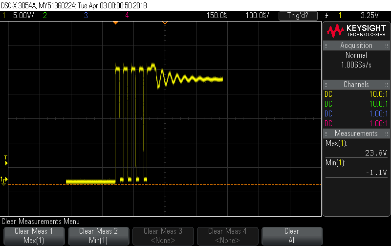
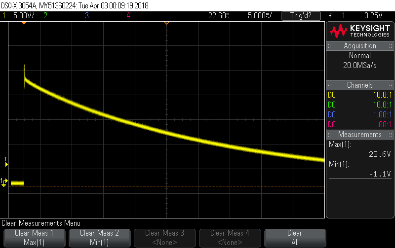
I am using the PGA460 in direct drive mode with a 40kHz transducer with a rather short decay time and am having difficulty obtaining an accurate frequency reading using the system diagnostics. I have played with the Window Length and Start Time, but can't seem to get a "good" reading. Any recommendations for getting the most accurate frequency reading?

  • Hi Andrew,

    The half-bridge driver does add a bit more complication to an accurate frequency diagnostic due to the clamped negative swing. One hardware modification you can make is to add a diode in series to OUTA (or the OUTx pin connected to the transducer) as shown in the following figure:

    This modification will allow the half-bridge driver to fully swing pos-and-neg during the decay-listen state for a more accurate frequency diagnostic. In addition, this will reduce the overall decay time to improve short range performance.

    I do recommend that you set your start time to be greater than 0us because of the immediate frequency shift of the driver releasing and the natural resonance taking effect. For a half bridge mode, a value up to the mid-code (700us) should be appropriate while using a short width length (3~9). The specific tuning of these values is dependent on your transducer and supply voltage.

    To manually monitor the frequency, you can use the TEST_MUX to output the analog front end output, and refer to the zero-crossing times to check how the frequency drifts during decay. This may help you select your start time and width length for the system diagnostic feature.

  • Hi Akeem,

    Thank you for your very detailed and useful answer. However, i don't think the diode will help in my case.

    I think part of my problem may be how little AC swing there is for my transducer when it is oscillating freely. Comparing my scope captures to your examples you can see that for my transducer the AC component comes nowhere near zero before it decays away. The first image is zoomed in, while the second is a very zoomed out version.

  • Hi Andrew,

    Another component to add is a damping resistor in parallel to your transducer. The damping resistor will more rapidly bias the resonance of the transducer to 0V as shown in my last post. In addition, the damping resistor serves as a bleed-out resistor to decrease the transducer's decay time.

    For details on how to select the damping resistor, refer to section 3.4.3 of the "PGA460 Ultrasonic Module Hardware and Software Optimization" appnote: www.ti.com/.../slaa732.pdf
  • Hi Akeem,

    Yes, I temporarily had the bleeder resistor removed in an effort to obtain an accurate frequency measurement.

    Below is how it looks with a bleeder resistor at the transducer (yellow) and at the Test Pin with the Analog Front End (green)

    When trying to measure the frequency on the oscilloscope with the Test signal, there is little to no consistency in measurements from period to period.

    Do you believe I should be able to obtain an accurate measurement based on what you see?

  • Hi Andrew,

    The waveform as you have shown does complicate the frequency diagnostic measurement. I highly recommend that you use the series forward diode at the OUTx pin connected to the transducer-positive terminal to enable full peak-to-peak swing during decay.

    The frequency diagnostic feature relies on the zero-crossing time of the decay profile. The external AC coupling capacitor on the INP path proves to be effective since your AFE output still toggles during decay, but adding the forward diode will improve the reliability/consistency of the measurement.

  • Hi Akeem,

    Sorry I didn't specify. That waveform is WITH the forward diode at the OUTA pin, so I guess this might be the best I can get, unless you have any other recommendations.

  • Hi Andrew,

    Another change you can try is swapping the OUTA and OUTB connections, such that OUTB is connected to the XDCR+ terminal, and OUTA drives the high-side PMOS. The advantage of this configuration is that OUTB always releases the transducer after pulling the XDCR+ to GND. OUTA releases the XDCR+ at VPWR, which is why the decay initially appears biased at VPWR rather than 0V.

    The EVM's daughter-card has not been updated to reflect this improvement, but if you refer to the schematic of the "PGA460 Mono-static Transducer Half-Bridge Driver Small Form Factor Design File" at www.ti.com/.../slac755 you will notice the change to the OUTx connections.

    Which transducer are you using? Are you optimizing the decay on your custom hardward or the EVM? The forward diode add-on to the OUTx channel should make more of an impact at a larger pulse count.
  • Akeem,

    Thanks for all your help, when comparing the EVM waveform to our own design I noticed the difference in the release and we are getting more reliable results on our board which utilizes this improvement.

    Thanks,

    Andrew