This thread has been locked.

If you have a related question, please click the "Ask a related question" button in the top right corner. The newly created question will be automatically linked to this question.

CCS/TDC1000-TDC7200EVM: Issue with impedance matching circuit

Part Number: TDC1000-TDC7200EVM

Tool/software: Code Composer Studio

Hello,

I have got the PCB printed for the impedance matching circuit for TDC1000-7200 EVM. I was unable to make it work. Certain issues are:

1. With out plugging in the impedance matching circuit the pulses show full 3.3V but as soon as I plug the board it comes down to 1V pulses.

2. In GUI I selected 4 pulses but when turning on impedance matching enable number changes to 5 pulses.

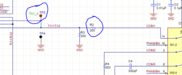
3. Right after R2 the pulses vanish not reaching the IC.

Any suggestions to make it work? Attached are some pictures.

  • Hi Prudhvi,

    Did you remove R41 and R42 from the TDC1000-TDC7200EVM? Those need to be removed when using the impedance matching circuit so that the TX and RX pins are not shorted together. I believe fixing this will solve all of the problems you have listed.

    Regards,
  • Hello Scott,
    I have tested the circuit with resistors removed, yet the issue remains the same. Any specific tests can I do so that I can understand more on why pulses are dying after R2 and also why the pulses have reduced their amplitude as soon as the circuit is connected?

    Regards,
    Prudhvi Sagar
  • Hello,
    I see a similar situation compared to this post but am not sure here e2e.ti.com/.../659664 . The PCB which is printed might be behaving in a similar fashion as that of the transducer reported. Can you suggest me from hardware point of view to add any components and physically how to add them (like I can do stacking) to try resolving this issue. Is there any impedance test I can carry out to quantify? I havent used the exact component models for the BOM as I was unable to find them at local vendor but have used the same values, could this be the reason? In the manufacturing of PCB high Tg was not available so Std. Tg was used.

    Regards,
    Prudhvi Sagar

  • Hello,
    The behavior observed looks similar to one in this post e2e.ti.com/.../631531 . My doubt is such low TX pulses can they be used for operation. Would you suggest me to change the resistor value? I am seeing no signal after the resistor is the behavior similar with your setup?

    Regards,
    Prudhvi Sagar

  • Hello,

    Is it possible to realize the impedance matching circuit on a bread board? Using TSSOP to DIP adapter for the switch.

    Regards,

    Prudhvi Sagar

  • Prudhvi Sagar said:

    Hello,

    Is it possible to realize the impedance matching circuit on a bread board? Using TSSOP to DIP adapter for the switch.

    Regards,

    Prudhvi Sagar

    Hello,

    There has been an issue from my side of soldering a wrong resistor. I have checked the final circuit and attached the final pulses I am getting at the transducers. I am getting about 1.5 V pulses finally. Kindly confirm if everything is fine.