This thread has been locked.

If you have a related question, please click the "Ask a related question" button in the top right corner. The newly created question will be automatically linked to this question.

PGA460: Configuration Procedure for GUI

Part Number: PGA460

Hi,

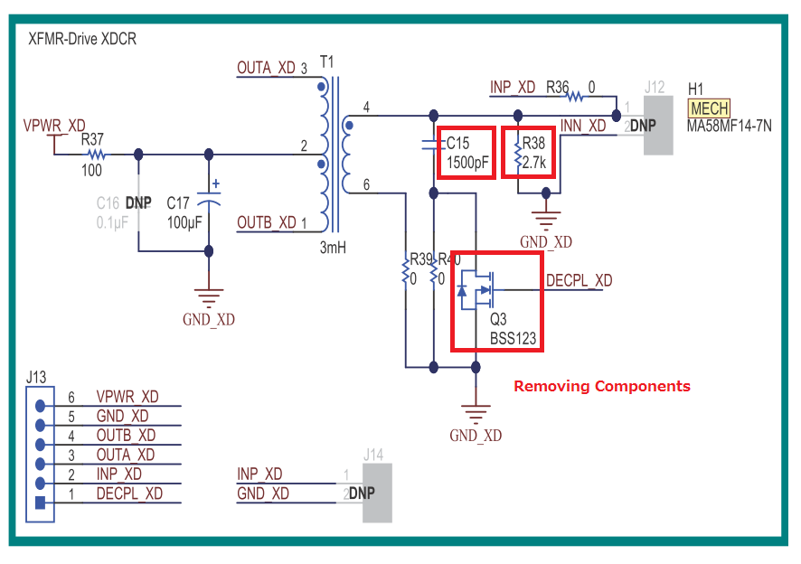
I have already got the transducer(Murata MA300D1-1) and the transformaer(Wurth 750316928) to realize the short range detection and the schematic refers to the following post.
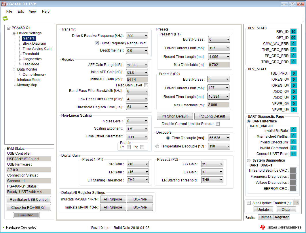
So, could you please tell me the configuration procedure for GUI using the BOOSTXL-PGA460 ?

PGA460: Short Range Detection
https://e2e.ti.com/support/sensor/ultrasonic/f/991/t/706906

Best regards,
Kato

  • Hi Kato,

    Attached is an example memory map configuration file I used when initially testing the Murata MA300D1-1.

    For option 1, I used a 9V supply at a 200mA driver current limit:

    GRID_USER_MEMSPACE-2017-05-26_143849.txt
    ;GRID_USER_MEMSPACE
    00 (USER_DATA1),00
    01 (USER_DATA2),00
    02 (USER_DATA3),00
    03 (USER_DATA4),00
    04 (USER_DATA5),00
    05 (USER_DATA6),00
    06 (USER_DATA7),00
    07 (USER_DATA8),00
    08 (USER_DATA9),00
    09 (USER_DATA10),00
    0A (USER_DATA11),00
    0B (USER_DATA12),00
    0C (USER_DATA13),00
    0D (USER_DATA14),00
    0E (USER_DATA15),00
    0F (USER_DATA16),00
    10 (USER_DATA17),00
    11 (USER_DATA18),00
    12 (USER_DATA19),00
    13 (USER_DATA20),00
    14 (TVGAIN0),88
    15 (TVGAIN1),88
    16 (TVGAIN2),88
    17 (TVGAIN3),00
    18 (TVGAIN4),00
    19 (TVGAIN5),00
    1A (TVGAIN6),01
    1B (INIT_GAIN),C0
    1C (FREQUENCY),64
    1D (DEADTIME),80
    1E (PULSE_P1),06
    1F (PULSE_P2),86
    20 (CURR_LIM_P1),15
    21 (CURR_LIM_P2),D5
    22 (REC_LENGTH),03
    23 (FREQ_DIAG),00
    24 (SAT_FDIAG_TH),EE
    25 (FVOLT_DEC),7C
    26 (DECPL_TEMP),0F
    27 (DSP_SCALE),00
    28 (TEMP_TRIM),00
    29 (P1_GAIN_CTRL),24
    2A (P2_GAIN_CTRL),00
    2B (EE_CRC),94
    40 (EE_CNTRL),00
    41 (BPF_A2_MSB),56
    42 (BPF_A2_LSB),72
    43 (BPF_A3_MSB),F3
    44 (BPF_A3_LSB),72
    45 (BPF_B1_MSB),06
    46 (BPF_B1_LSB),47
    47 (LPF_A2_MSB),7C
    48 (LPF_A2_LSB),D3
    49 (LPF_B1_MSB),01
    4A (LPF_B1_LSB),97
    4B (TEST_MUX),00
    4C (DEV_STAT0),80
    4D (DEV_STAT1),00
    5F (P1_THR_0),88
    60 (P1_THR_1),88
    61 (P1_THR_2),88
    62 (P1_THR_3),88
    63 (P1_THR_4),88
    64 (P1_THR_5),88
    65 (P1_THR_6),84
    66 (P1_THR_7),21
    67 (P1_THR_8),08
    68 (P1_THR_9),42
    69 (P1_THR_10),10
    6A (P1_THR_11),80
    6B (P1_THR_12),80
    6C (P1_THR_13),80
    6D (P1_THR_14),80
    6E (P1_THR_15),00
    6F (P2_THR_0),88
    70 (P2_THR_1),88
    71 (P2_THR_2),88
    72 (P2_THR_3),88
    73 (P2_THR_4),88
    74 (P2_THR_5),88
    75 (P2_THR_6),84
    76 (P2_THR_7),21
    77 (P2_THR_8),08
    78 (P2_THR_9),42
    79 (P2_THR_10),10
    7A (P2_THR_11),80
    7B (P2_THR_12),80
    7C (P2_THR_13),80
    7D (P2_THR_14),80
    7E (P2_THR_15),00
    7F (THR_CRC),28
    EOF
    

    For option 2, I used a 3.3V supply at a 500mA driver current limit.

    You can import these settings into the PGA460 GUI as a starting point for your evaluation and configuration.

    The procedure to optimize the PGA460 parameters is discussed in section 4 of the "PGA460 Ultrasonic Module Hardware and Software Optimization" app note ( ).

  • Hi Akeem-san,

    Thank you always for your support.

    I will try to modify the BOOSTXL-PGA460 daughtercard as below, then I am planning to use the BOOSTXL-PGA460 with USB power supply to demonstrate to our customer.
    In this case, should the driver current limit be applied ?

    Best regards,
    Kato

  • Hi Kato,
    When using the USB boost supply to evaluate/demonstrate the EVM, the preset 1 or 2 current limit should not exceed ~300mA. Otherwise, the device may enter an undervoltage condition due to the limited current output of the USB output. If you want to increase the preset driver current capability of the EVM when using the USB boost circuit, you can add a large electrolytic capacitor (i.e. 220uF) in parallel to the output of the boost circuit.
  • Hi Akeem-san,

    Thank you for the information.

    I understood and will contact you if I have additional questions.

    Best regards,
    Kato

  • Hi Akeem-san,

    As a result of evaluating my test board using BOOSTXL-PGA460 with USB power supply, it worked normally for Preset1, but didn't work for Preset2.
    The GUI setting is shown as below, so I didn't modify the register setting which you provided me.
    Could you please tell me that reason why PGA460 doesn't work normally for Preset2 ?
    For Preset1, it seems to be able to detect from a distance of 7cm.

    Best regards,
    Kato

  • Hi Kato-san,

    Does preset 2 work properly if you are not running from the USB supply?

    If preset 1 and 2 are truly identical, there is no reason one command should not be working if the other is.
    When you say the P2 command does not work, do you mean that the PGA460 device completely ignores the command, or does the device actually excite the transducer, but returns faulty data? I see the digital gain settings for P2 are set to x1, while P1's are set to x16.

    If the issue is performance related, then try increasing P2's digital gain settings to match P1 (set both SR and LR Gain to x16).
  • Hi Akeem-san,

    Thank you for the information.

    For preset2, I will try to check with an external power supply next week as I checked only this behavior with the USB power supply.
    In addition, I confirmed that PGA460 works properly if setting x16 to "SR Gain" and "LR Gain" for preset2 with the USB power supply, in other words I could visually confirm that the received wave exceeds the threshold value.
    By the way, you mentioned above "For option 2, I used a 3.3V supply at a 500mA driver current limit", so does this mean that PGA460 is powered by an external source 3.3V at J5 ?
    I found in the user's guide that PGA460-Q1 EVM should be applied as an external voltage source from 6V to 28V, so I am confused.

    Best regards,
    Kato

  • Hi Kato-san,
    The PGA460 requires 6-28V to operate. Connect an external supply voltage within this range to the J5 connector.
    When using the USB-boost circuit, the 5V USB supply is boosted to 7.2V.
    The 3.3V rail is generated by a 5V-to-3.3V LDO circuit on the LaunchPad, and is only used to power the MSP430 MCU and supporting EVM circuitry. Do not connect 3.3V to the PGA460 VPWR pin.
  • Hi Akeem-san,

    Thank you for the explanation.

    I understood, so I will verify Preset2 and get back to you next week.

    Best regards,
    Kato

  • Hi Akeem-san,

    For Preset2, I verified PGA460 by applying an external source 9V at J5 to VPWR and setting x16 to "SR Gain" and "LR Gain".
    As a result, PGA460 worked normally, so I will optimaize the settings in the future.
    In addition, the floor noise was also improved.

    I greatly appreciate your cooperation.

    Best regards,
    Kato