This thread has been locked.

If you have a related question, please click the "Ask a related question" button in the top right corner. The newly created question will be automatically linked to this question.

DRV5011: Pin number direction and some explanation of functionalities requested

Part Number: DRV5011
Other Parts Discussed in Thread: TMAG5110

Hi,

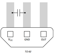
I want to use DRV5011 TO-92 Package. I found the footprint details from datasheet. I'm little confused with the number direction from this image.

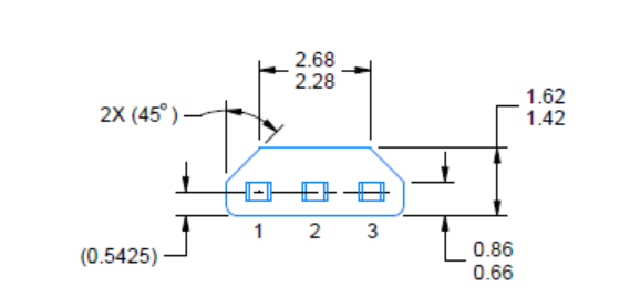
Can anybody help me. Is this bottom view or top view?

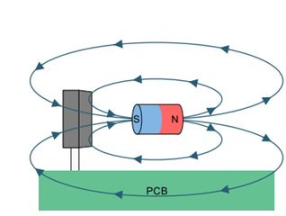
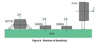
Also little explanation of function w.r.t. to magnet N-S will be appreciate.

Thanks

Dip

  • Hello Dip,

    Due to a holiday there will be a delay in responses until tomorrow. Sorry for any inconveniences this may have caused thank you for your understanding.

    Best,

    Isaac

  • Dip,

    Thank you for your question.  I can see you you might interpret the drawing either way. In the same dimensions drawing you refer to, we also see a front view of the package (the front is the beveled face).  Since the leads are numbered in both drawings we can then determine that the image you provided is that bottom view.

    In the layout section we also have a top down view which is shown here where pin 1 (VCC) is on the left.  I have also verified this against the layout on a known PCB.

    Thanks,

    Scott

  • Thanks for the clarification and confirmation.

    Further to this.

    I have checked the datasheet for functionality of sensor w.r.t the magnetic field but not able to get confidence with my understanding

    I would be thankful If you can explain the operation in some simple way. I have confusion regarding magnet polarity. I need to get pulse from Sensor during operation. Magnets shall be placed in circular plate.

    Thanks

    Dip

  • Dip,

    The device considers a positive input to be directed from the back towards the front of the package.  Because of how the magnetic field lines wrap around the magnet, presenting a South pole to the face of the sensor will generate this effect.  Similarly, a North pole could be presented to the back of the package for the same device behavior.

  • Thank you very much  for your accurate answer which helps me to get clear understanding in my application.

    I feel that It will be difficult to consider this package or sensor for my application as I have very limited space to place it on PCB and two of same sensors needs to place such a way it should generate square pulses in sequence with some phase difference. I am sharing the PCB image with sensor mounting details here for your reference.

    Could you suggest me the similar low cost solution which full fill my application? Or any suggestion for improvement are most welcome. I have constraint of space and I have to place sensor in this way only.

    I am thinking that SMD package should help me, Right?

    Thanks

    Dip

  • Dip,

    You may be able to use a SMD type package, but for most latches this will result with the device not being sensitive to the same field component 

    Depending on your magnet and the motion you are capturing, this might still be possible with any of the other package variants. The X2SON or DSBGA packages are quite small and could likely fit easily in your application.  You will need to carefully consider the field you are observing to make sure there is a measurable component

    Another option is to use TMAG5110, which is a 2D sensor.  This device has three variations (XY, YZ, ZX).  Any of these devices might be used to detect a field component parallel to the surface of the board.  If the XY variant were selected, the device could be placed as needed to detect the field component you are wanting to sense.

    Thank you,

    Scott