This thread has been locked.

If you have a related question, please click the "Ask a related question" button in the top right corner. The newly created question will be automatically linked to this question.

TMCS1101: Why i do not see the change of the outpue voltage

Part Number: TMCS1101

Hi all

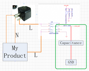
I use the TMCS1101A4B to detect the current of my product.  The schematic just as below

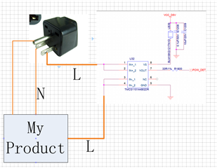
My product is 10W and the current is maybe 90 mA

And the slope rate of TMCS1101A4B is 400mv/A, So theoretically i can see 45mV change in the output line

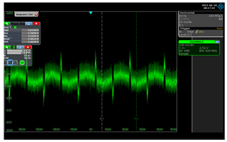
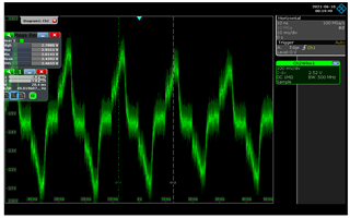
But in my test , i can not see any change when i  connect  my product or not

So Does it is correct?

Thanks.

  • Liu,

    I believe the issue you are having here is noise related. From your schematic, it looks as though you are not filtering at the output. For the entire BW of the device, the noise can be calculated as 

    P2P Noise (Vpp)= Noise Density ((µA)/√Hz) × √(Device Bandwidth) × Sensitivity (V/A)×6.6

    With values for the A4 from the datasheet, peak to peak noise current value of 420mA, which means I believe your attempted measurement is getting lost in the noise floor of the device. 

    You should be able to rectify this by filtering the output to reduce the device BW, which should improve the noise floor as per the equation above. 

  • Thanks for your reply

    But how can i design the filter. Could i use a RC filter to reduce the noise? just as below?

    if so, How to calculate the value of  capacitance? 

  • By the way i also try to connect a 300W product to the chip, but i also can not see any change of the output voltage

    So i think it has no relationship with the noise. 

    i want to confirm that i connect line of fire to the IN+ and IN- . just connect the chips in series between the wires of fire. So Does it is correct?

    Thanks.

  • Hi all 

    I am update some new result

    i test the outpur voltage by the Oscilloscope. And  i find some new phenomenon

    1、When i connect a product that power is 11W, and the output voltage is just as below

    2、When i connect a product that power is 150W, and the output voltage is just as below

    3、My input voltage is AC voltage 220V ±10% , and frequency is 50Hz

    So i think when the load power increase, the Swing of the output voltage will be increase . but the mean value and rms value of the output voltage nearly unchange. Does it is correct?

  • Liu,

    Yes a 1st order LPF would be fine here. You can see a response of the output to a filter in section 9.3.3.4 of the datasheet. As per the equation I posted in my last post, the implementation of the filter will effectively limit the BW of the part at whatever value you choose to implement. By limiting the BW in this way, the noise will also effectively be reduced by that action. You will need to decide a good place to design the filter to limit noise as much as possible while balancing that with how much dynamic response you want/need the device to maintain. 

    Regarding the latest images, as you are providing a sinusoid to the input, I agree that the mean value should not change. This will stay constant, at the offset provided by the part. As you are using the B version of the device, the output is set at 0.5Vs, so this should remain your mean provided the input remains a sinusoid. 

    The RMS value will shift however. Recall that for a sine wave with a DC offset, the RMS value is calculated as

    and while the DC term (a0 = 2.5V) will remain constant, the peak value of the wave (a1) will increase as the output response grows. Therefore your RMS value will increase with the output response.