This thread has been locked.

If you have a related question, please click the "Ask a related question" button in the top right corner. The newly created question will be automatically linked to this question.

AFE3010: GFCI application for leakage sensing

Part Number: AFE3010

Hi team,

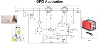
My customer is using AFE3010, but they have an question on the load switch (relay) placement, this shall be placed before relay or behind?, it seems require 2 CT circuit, do we have other suitable solution?

  • Hello Oliver,

    The AFE3010 needs to be placed behind the load switch (so on the line side, not the load side). The reason is so the AFE3010 can still be powered up and running self-tests, if the load switch is opened, or else user would not know if the GFCI is working before closing the load switch so they can power and use their loads (toaster or shaver as shown in image).

    If manufacturer wants the AFE3010 to be able to sense neutral-to-ground (N-G) faults, then they must use two CTs. If they don't care about sensing N-G faults, they could remove the 200:1 CT entirely and system will work normally and sense hot-ground faults, but it will not be able to sense N-G faults.

    Hope this helps.

    Best,

    Peter

  • Hi Peter,

    Thank you for your reply on this with details.

    My customer would like to know that datasheet table 5, is that design suitable for 230 VAC application?

    If table4 and table5 is for 120VAC, what we need to change for 230VAC application? Thank you.

    Regards,

    Oliver

  • Hey Oliver,

    Table 5 is the BOM for a 120VAC line application. In the "Description" column, I mention whether or not the power rating of the respective component should be increased for higher line voltages. Customer can look for these components to know what to change. These components are: C11, D1, D2, D4, Q1, R1, R2, R3, R4, R8, R11, and R12 (refer to Figure 15 in datasheet as the schematic).

    C11, D1, D2, D4, and Q1 require voltage ratings that in general can withstand the peak line voltage.

    R1, R2, R3, and R4 require larger power ratings, especially R1 and R2. For R3 and R4, peak power rating is determined by multiplying the peak AFE3010 supply current (IDD_peak) with the peak voltage drop (Vdrop) across them. IDD_peak = IQ,max + I_scr, max + I_alarm,max where I_scr is the drive current out of SCR pin (3mA max, see section 6.5) and I_alarm (~5V/R9) is the drive current out of ALARM pin. Since ALARM and SCR should not be fired a lot, you can approximate total IDD as 2mA. So voltage drop across R3||R4 (Vdrop34) is IDD*R3||R4.

    The drop across R1||R2 (Vdrop12) is larger and can be approximated as Vdrop12 = Vline_pk - VDD - Vdiode -Vdrop34 = 170V-20V-0.7V - Vdrop34. Thus current through R1||R2 = Vdrop34/(R3||R4). The 

    R8 resistance can be scaled up to achieve similar fault-test current (120VAC/10.5kΩ = 11.42 mA RMS).

    R12 resistance should be scaled up accordingly to achieve similar input leakage current (120VAC/1MΩ = 120uA RMS).

    R11 resistance should be kept the same, but with increased power rating according to equation listed in Description Column of Table 5.

    Please post back if you have more questions.

    Sincerely,

    Peter

  • Hi Peter,

    Thank you for your help on this. Customer got some following questions, please kindly share some input.

    1. Customer wants to inform MCU once the leakage happens, is Alarm pin for this purpose? Or we have other suggestion?

    2. From the datasheet, it is showing D4, R8, Q1. What is the distance should be to fit safety regulation?

    3. From the datasheet chapter 8.2, how to choose a suitable solenoid?

    4. Could you please teach me what is SCR mentioned in the datasheet? What device it is?

  • Hello,

    1. The alarm pin really only will show if there is an ALARM or end of life condition as described in datasheet.

    MCU could monitor the SCR pin voltage to determine if there has been a leakage greater than 5 mA threshold. Or they could read the OUT voltage to directly calculate the linear leakage. 

    2. There is no distance requirement I am aware of as this is a system level requirement from the standard.

    3. The solenoid needs high enough power rating to conduct the SCR current for at least a couple line cycles at any point. But it also needs enough mechanical strength to pop the mechanical load switch of the GFCI product.

    4. SCR stands for silicon controlled rectifier and is a standard type of semiconductor IC. It is meant to short current through solenoid to make an electromechanical disconnection.

    Hope this helps.

    best,

    Peter