


This thread has been locked.
If you have a related question, please click the "Ask a related question" button in the top right corner. The newly created question will be automatically linked to this question.
In automatic transmission gear shifters, the standard positions are park, drive, neutral and reverse. The multiple forward gears are replaced with just one or two positions - drive and a low gear setting in others. Nowadays, many vehicles also include a manual mode with plus and minus settings in the automatic transmission for drivers to have more control.
Standard lever gear shifters
Most of the vehicles use a standard lever for gear shifting where the lever is moved in a straight line or zig zag pattern to select the different positions (Park, Reverse, Neutral, Drive, Low and Manual setting) as shown in figure 1.
![]()
Figure 1: Standard Lever Gear Shifter
Hall-effect sensing is the preferred choice of technology for position sensing of the gear shifter.
In the standard lever-based systems, the gear shifter is mostly designed using simple Hall-effect switches to set the appropriate gear in the transmission as shown in figure 2. The magnet is attached to the lever and as it slides from one position to another, the output of the associated hall-effect switch changes state to switch the gears inside the transmission. Depending on the number of gear positions, 5-6 hall-effect switches are needed to implement this system.
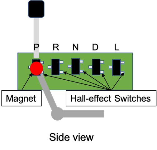
Figure 2: Standard Lever Gear Shifter with multiple Hall-effect switches
Three dimensional (3D) magnetic sensors
Now with the availability of 3D magnetic sensors, designers can save space and cost and simplify their design by using 3D position sensing in place of a linear array of Hall-effect switches as shown in figure 3 below. With the 3D hall sensor, we use the angular position of the magnet with reference to the 3D Hall-effect sensor for the different gear positions. Also with 3D sensors, cheaper ferrite magnets can be used to lower cost compared to more expensive Neodymium magnets.
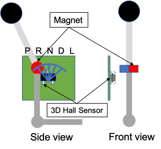
Figure 3: Standard Lever Gear Shifter with 3D Hall-effect Sensor
Dial type gear shifters
Some of the newer automobiles now come with a dial or round knob for gear shifting in place of the standard lever as shown in figure 4 for sleeker look and to save space in the center console.

Figure 4: Dial or knob type Gear Shifter
The dial or knob design can also be implemented with either multiple Hall-effect switches (figure 5) or with just one 3D Hall-effect sensor (figure 6) like the standard lever shifters. The 3D magnetic sensor approach once again allows for more mechanical flexibility and ease of design. The increased need for safety in automotive electronic systems is driving need for redundant architectures and this fits well with a 3D Hall-effect sensor for space constraints – two 3D sensors compared to 10-12 Hall-effect switches on the PCB.
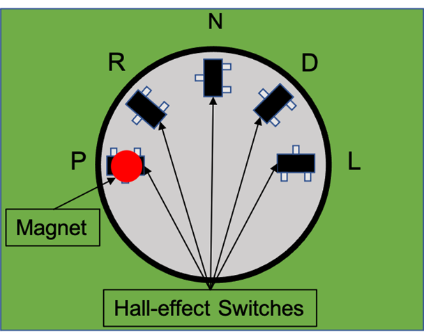
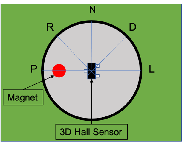
Figure 5: Dial Gear Shifter with Hall switches Figure 6: Dial Gear Shifter with 3D Hall Sensor
Get started with TI’s hall-effect magnetic sensors
No matter what type of gear shifter you are designing, TI has the right Hall-effect sensor for your design – the DRV5021-Q1, a 5V Hall-effect switch or the DRV5023-Q1, a high voltage (up to 38V) Hall-effect switch . In the case of 3D Hall-effect sensors, the TMAG5170-Q1 is the ideal product with integrated cordic angle calculator and safety diagnostics that assist with ISO26262 ASIL-B compliance with a single IC or higher ASIL levels with two ICs in a redundant architecture.
Additional Resources
