This thread has been locked.

If you have a related question, please click the "Ask a related question" button in the top right corner. The newly created question will be automatically linked to this question.

HDC2021: Temperature/Humidity Issue

Part Number: HDC2021
Other Parts Discussed in Thread: HDC2022,

We have been using HDC2021/HDC2022 in our products and the product was working with expected temperature results since the assembly and all of a sudden the temperature had fallen down by 8 deg C with respect to reference .We have done various test cases to check this, when we have altered the environment temperature , the sensor is responding but again fallen down by 8-10 deg with respect to reference. For ex: The device was reporting 23 deg C where reference was 23.2 for more than 6 months and all of a sudden  temperature of a sensor fallen down to 15 deg C where the ref being same.
Have done multiple tests ,but sensor didn't work.

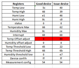
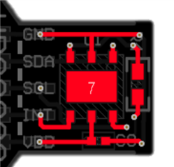
We have shared all our sensor location gerber images , schematic setup to TI forum . Also team have asked to read default register  if this issue happens and FYI we are doing it and reading default registers .
Continuously we have seen this issue in 4- 5 sensors over the period of time .

What could be the reason for this sudden failure of sensor which was accurate since the assembly. Its urgent ,so please help us to find out the root cause.
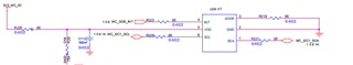
  • Dear Sowmiya - 

    if the red circle you show on the board is supposed to to be for the thermal pad, you should re-lay your board out and use actual CAD symbol from us. 

    See CAD symbol: https://vendor.ultralibrarian.com/TI/embedded/?gpn=HDC2021&package=DEB&pin=6&sid=017817f8a5430077b97d553b377803073001306b00bd0&c=1 

    and datasheet https://www.ti.com/lit/ds/symlink/hdc2021.pdf 

  • Hi Josh ,

    The CAD is as per your files and all the settings are as per datasheet .
    As I mentioned earlier we are facing sudden drop in temperature and what could be reason for it  .We have faced this issue in more than 10 sensors and it would be grateful if  you assist us on this.

    Thanks,
    Sowmiya

  •  Josh ,

    The CAD is as per your files and all the settings are as per datasheet .
    As I mentioned earlier we are facing sudden drop in temperature and what could be reason for it  .We have faced this issue in more than 10 sensors and it would be grateful if  you assist us on this.
    FYI  our operating voltage is also greater than 2.7 V . Do we need to set any custom settings of the register 

  • Dear Sowmiya -

    so then, please show the layout as you actually have it. and if possible, logic capture of the data bytes which are off. 

  • Can you explain me this even more in detail .
    Also we are suspecting some I2C issue and feel that some registers are getting corrupted .Is there any possibility to lock the registers ?

  • Sure I can provide you . IS there are any  register settings  that we can use to prevent this misbehavior .  Also we have kept the operating voltage greater than 2.7 V . Can you help us with custom settings if any  for preventing the register corruption ?

  • Sowmiya - 

    First, please confirm your layout is correct, as requested. 

    If you want to also send a readout of all the registers via logic analyzer, that would be best, for us to help you. 

  • HDC21.pdfPlease find the layout and please help with the above issue. We have seen almost 10 sensor failures in the field and it is highly affecting us. So let us know the solution for this

  • Josh,

    Please share me your email ,so that I can share you few more details. I am attaching log data of the register and here we found temperature offset adjustment register corrupted. Why is this register getting corrupted where we haven't used this . So please check and give us the solution .7607.HDC21.pdf


  • Dear Sowmiya - 

    I think you need to repair your layout before proceeding too much further - the pad underneath the part is not round, and from your attachment, it appears that you have made the PCB this way. 

    Regarding the registers - it appears like the registers were written in both cases, not corrupted - please compare what you have presented against page 20 of the datasheet https://www.ti.com/lit/ds/symlink/hdc2021.pdf 

  • No Josh ,  Please check all layers .The hole is below thermal pad and we haven't soldered the pad .That is not causing the issue .Even if this causing the issue then why does this hole is causing  issue in few sensors and thousands of other sensors are reporting as expected. We have earlier confirmed the layer settings with TI earlier during the chip design in PCB and it is all right. Why do you suspect this ?
    Also we haven't touched any offset adjustment register and it got automatically set to 80 and temperature result got decremented by  20 deg. So we strongly suspect register corruption. Please consider this as a serious issue and please do the needful 

  • Sowmiya - 

    Your layout looks very different from what is given for the layout for the part placement - I did look at your attachments.

    at any rate - it is always your design choice to make it correctly or not. 

    To be clear - from what you have provided - this is the difference I can see here, which gives me cause to be concerned on your behalf.. 

        vs. 

    With regards to the registers - it is obvious your firmware must be writing the registers to begin with. I would suggest that you have a detailed looks with a logic analyzer, from power up, and capture what your firmware is doing and compare it to your specific design/requirement documents & flow chart, for the behavior you intended. That should show you where the error is and if you need help analyzing that, we can of course take a look with you, if you can share those - once they are captured. 

  • Josh ,

    Thankyou

    To clarify you , we haven't written anything to temp offset adjustment register .But it got written all of a sudden at a point and it got recovered only when we power cycle it or reset the register.
     Also , I just want to clarify why is the minimum frequency 10 KHz and not below it ..can't we work in frequency below 10 KHz ? 

  • Hi Sowmiya,

    Could you please send me your startup command sequence and also send me all the default register values after power up? I would recommend issuing a POR and reading all the registers immediately to ensure nothing is being written to the part. 

    Regards,
    Pavani Tenneti

  • Hi Pavani ,

    This is our command settings during initialisation ,
    Configuration register (0x0E) - value - 0x54

    Measurement register (0x0F) - value - 0x01
    Interrupt Enable( 0x07) - value - 0x60
    Temp High limit( 0x0B) - value - 0x70
    Temp low limit( 0x0A) - value - 0x45.

    Please check and let me know your feedback. As mentioned earlier  please clarify why the nominal frequency range is > 10KHz and not less than this.

    Thanks,
    Sowmiya

  • Hi Sowmiya,

    The initialization sequence looks correct, however if you are using the part below the frequency specification, there is a chance that the registers could read FF. This part is characterized at 10KHz and above and we recommend you use it according to datasheet specifications. 

    Could you also send us scope shots of the register read commands? I think there is a timing issue that is causing this register corruption and we can analyze that by looking at scope shots. 

    Regards,
    Pavani

  • Hi Pavani ,I have shared the scope images of SCLK, Risetime of the clock signal.Standard operating range of I2C is from 0 to 100KHz.But why is the nominal range here is above 10KHz?

    Please check the below images and let me know why.


  • Hi Sowmiya,

    Our devices have a minimum frequency due to the SMBus Timeout feature. Hence we don not recommend using this device below 10KHz. 

    I only received one scope shot and the other image could not be opened. Could you please send me a zipped file containing all the scope shots?

    Regards,
    Pavani Tenneti

  • Hi Pavani ,

    Thanks.

    I am attaching  the zip file as you asked .Can you also let me  know in SMB Timeout feature what happens if we use the frequency below 10 KHZ just for clarification.I2C_pic.rar

  • Hi Sowmiya,

    If the I2C transaction takes too long to complete, timeout will cause the sensor to stop responding. Depending on when the timeout occurs and what type of transaction, you might see NACK or receive 0xFF data.

    thanks,

    ren