This thread has been locked.

If you have a related question, please click the "Ask a related question" button in the top right corner. The newly created question will be automatically linked to this question.

DRV5032: Digital-Switch Hall Effect Sensors in RFID application

Part Number: DRV5032
Other Parts Discussed in Thread: DRV5012

We would like to use Digital-Switch Hall Effect Sensors in our RFID readers as tamper protection.

RFID means freq band HF (13.56MHz) and LF (125kHz) together. We need have to investigate both of freq band.

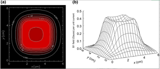
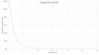
As you know, antenna field is contiunuos changing, the sinusoid signal in the field with period much more shorter than sensor sampling range. The peak magnatic field could reach the sensor Bop, Brp levels.

RFID antenna field could disturb the sensing of sensor at peak points.

The target sensor types are 

DRV5021A2QDBZR
DRV5021A3QDBZR
DRV5023BIQDBZR
DRV5032AJDBZR
DRV5032ZEDBZR
DRV5033FAQDBZR
DRV5033AJQDBZR

Could you tell me any info about interference?

Will antennas magnetic field disturb the sensing?

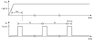
Could you tell me more about sensor internal sampling process (instantaneous or average is used)?

What kind of sensor type do you prefer for our application?

References:

Attila

  • Attila,

    The devices will average the input over the duration of the sampling period.  If that average exceeds the BOP threshold at the completion of the sample time, then the device will trigger.

    This means that peak bursts of AC magnetic fields in excess of BOP will not necessarily cause a trigger event provided that the nominal state is typically less than BOP.  

    Additionally, for the Hall Effect, the sensor is only sensitive to the component of the magnetic field normal to the Hall-Element.  For instance, we might force a current through a conductor in the Y direction, apply a magnetic field in the Z direction, and measure a voltage difference across the element in the X direction.  If the field from the antenna is not in the direction of sensitivity of the sensor, then there will be no impact to the sensor.

    There are a few approaches to this application.  If your goal is to detect case openings, then a magnet might be placed to keep a Hall-effect switch in the BOP state.  If placed close enough, the magnetic field would likely not be influenced enough by the RFID to cause a BRP event.  However, once the package is opened and the magnet is removed from the vicinity of the sensor, then you would be able to detect the tamper event by detecting the BRP condition.  In the event that this is a battery powered operation, this would operate best using a device with push-pull outputs.  Of the devices you are considering, this  would indicate DRV5032 as the best choice.  Otherwise, an open-drain output will draw a constant current through the pull-up resistor.

    Another approach is to place the magnet outside of the BOP range of the sensor.  If the magnet is forced to pass the sensor during a lid open event, then the device may idle in the release state during a normal condition.  For this configuration, a latch type device (like DRV5012) may be useful to consider.  Latch devices retain their current state until the opposite pole is presented to the sensor.  For example, if the lid close condition presents a downward vector to the device (BRP) and the magnet passes by the sensor during the lid open in a way to cause an upward vector (BOP) as it opens, then the device will trigger.  Once triggered, the output will remain low (even if the magnet is removed) until the lid is properly closed where the downward vector is presented again.

    Thanks,

    Scott

  • Hi Scott,

    Thank you for ideas.

    The devices will average the input over the duration of the sampling period.

    Are you talking about Tactive duration?

    Tactive=40us (Active time period) at DRV5032, which is 5 times longer like Tperiod of freq of 125kHz.

    Tactive=40us (Active time period) at DRV5032, which is 542 times longer like Tperiod of freq of 13.56MHz.

    I think, I understand well the physics behind of sensors. The best position for HAL sensor, if antenna is exactly placed bottom side of PCB, as near as possible to top side HAL sensor. In this case, antenna magnetic vector has minimal effect (perpendicual) for sensor. Am I right?

    Attila

  • With the fields as you have drawn them there should be minimal impact as the expectation is that this field is primarily parallel to the surface of the PCB.  If placed in the ideal location this would result in no input to the device.

    For DRV5032 Tactive is the time where the device is actively sampling the magnetic field.  This is much shorter than the sample interval.  During the time where ICC is low, the device is in a low power state and not performing any conversion.

    Thanks,

    Scott

  • Sorry, but it is not clear for me. How long does it take, where sensor integrates the magnetic field?

  • Sorry, it is only during Tactive (40 us)