Other Parts Discussed in Thread: TDC1000
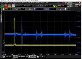
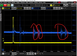
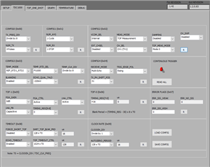
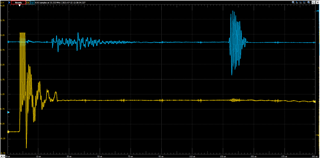
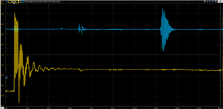
As shown in the figure below, I used the TDC1000-C2000EVM for sound speed measurements, and in yellow I connected the TX1/RX2 signals directly to the oscilloscope. The other is the blue one is the COMPIN signal. The latter signal I am not sure if it is an echo signal. Because these signals are constantly moving without me changing the distance the ultrasound travels. The signal in the picture is a transient signal that I intercepted.