This thread has been locked.

If you have a related question, please click the "Ask a related question" button in the top right corner. The newly created question will be automatically linked to this question.

LDC1000EVM: How to communicate directly with the EVM?

Part Number: LDC1000EVM
Other Parts Discussed in Thread: LDC1612, LDC1312, LDC1314, LDC1614, MSP430F5528, MSP430F5529, LDC1041, LDC1051

Hello everyone, I hope you are doing well.

I am posting this issue here as per the instructions of TI support.
This post is a follow-up to the Sensing Solutions EVM GUI not working with LDC1000EVM which was unresolved.

As per the question title, I would like to find out how to communicate with the LDC1000 device without using the Sensing Solutions GUI.

Some background first:
In the previous thread (GUI not working), I was forwarded to the Inductive Sensing GUI FAQ which discusses “How can I communicate directly with the MSP430 on the LDC1612, LDC1614, LDC1312, or LDC1314 EVM?”
There it discusses communication with the LDC13xx/LDC16xx EVMs using asynchronous serial protocol.
On the other hand, the LDC1000EVM uses SPI protocol to communicate, so I was unable to directly apply these instructions to my application.

Also as mentioned in the previous thread (GUI not working), even though I was unable to connect the EVM to the GUI, when I power up the EVM, and place a metal object next to the sensor, the LED indicator still comes on.
This suggests that the EVM hardware is functioning as expected.

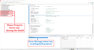
So, I decided to connect the logic analyzer to the EVM to determine what commands are being sent from the MSP430F5528 MCU to the LDC1000 sensor IC.
I also obtained the LDC1000 Firmware Library for the MSP430 – SNAC059.ZIP on your website as reference for comparison.

With that in mind, I connected the LDC1000EVM to the logic analyzer by soldering on some wires to the pads as shown in the image below.

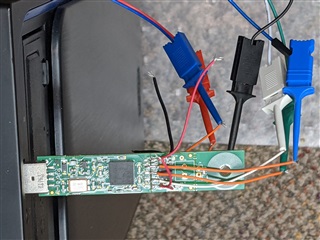
The Logic analyzer was setup to trigger on an CSB falling edge, and then armed.
The EVM was then powered up by plugged it into the PC’s usb port, and I was able to capture the SPI commands being sent to the LDC1000 during the device startup as seen below:

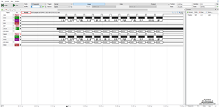
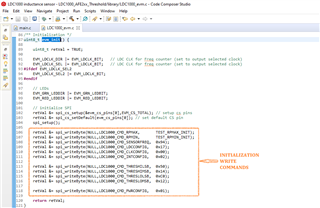
These first set of SPI commands from the image above match the firmware code’s spi_writeByte(…) commands being sent to the device within the evm_init() function code found in the LDC1000_evm.c file seen in the image below.

Also, subsequent SPI commands such as the one shown in the image below show that the MCU is sending read commands, and the sensor IC is sending data from it registers.

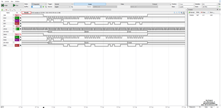
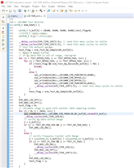
These commands correspond to the spi_readBytes(…) commands being sent to the device within the evm_test() function code found in the LDC1000_evm.c file seen in the image below.

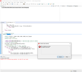
This suggests that on power-up, the MSP430F5528 MCU and the LDC1000 sensor IC are communicating with one another, even though the Sensing Solutions GUI is unable to communicate with the EVM.

Initial Questions:
So my questions is as follows:

  1. How do communicate with the LDC1000 device without using the GUI?
  2. How do I set up the to be able to configure it for prototyping?

Cheers

JC

  • Hello JC, 

    You have 2 main options for communicating with the EVM without using the GUI.

    1. You can write your own firmware for the MSP on the EVM and flash it to the board. You can use the existing firmware as a template and create the needed functionality. You can also use CCS to debug and read the data from the device. 
    2. You can separate the board at the connection between the MSP and the LDC1000. The board is perforated where you soldered in so you can break it off and use your own external SPI connection without the MSP. This is also helpful for prototyping depending on what you are wanting to do. 

    As for configuring for prototyping, you just need to determine if you are keeping the SMP section attached or using an external controller. From there, you just program the board as needed and connect it to your prototype. The sensor coil also snaps off if you would like to prototype with a different coil. 

    Best Regards, 

    Justin Beigel

  • Hi Justin

    I appreciate the quick reply.
    Thanks for the Prototyping information, I will use that moving forward.

    Also thank you for laying out all the methods of communicating with the EVM without using the GUI.

    use CCS to debug and read the data from the device

    Now I tried to do as you suggested before posting this question to the forum, and I ran into some issues while running the debugger.

    Some Background:
    First I imported the firmware projects into CCS as seen in the picture below.

    From the image we see the following:

    1. The EVM I have uses the MSP430F5528 but I don't see it listed here.
    2. Some of the projects error out when I build them. 
    3. The remaining projects give a "MSP430: Error initializing emulator: No USB FET was found" error when trying to debug them.


    Questions:

    1. Which firmware projects are compatible with the MSP430F5528 for debugging (if any)?
    2. If the projects that error out during the build are compatible, how do I fix them (each one has their own error message so will post them if the project is compatible)?
    3. Assuming the projects that error out when I try to debug them are compatible:
      1. What does the "MSP430: Error initializing emulator: No USB FET was found" error message mean?
      2. How do I fix it?

    Thank you for your help so far, and awaiting your response

    Cheers

    JC

  • Hello JC, 

    The MSP430F5528 and MSP430F5529 are very similar so you should be using the projects with the F5529 in their name. 

    Do you still have the "No USB FET" error when using any of the 3 F5529 projects? 

    Best Regards, 

    Justin Beigel

  • Hi Justin

    Thanks for the clarification on which projects to run.

    So I reran each of the F5529 projects, namely:

    • LDC1000_F5529LP_DRDY
    • LDC1000_F5529LP_LowSpeed
    • LDC1000_F5529LP_SENT_USBLOGGING

    and they all gave me the same popup window as seen in the image below.

    So unfortunately I am still getting the same error message.
    Any recommendations on what I can do to fix it?

    Cheers

    JC

  • My apologisies.

    I forgot to include the appropriate reference links in the original post.

    Sensing Solutions EVM GUI not working with LDC1000EVM

    The link in HERE

    “How can I communicate directly with the MSP430 on the LDC1612, LDC1614, LDC1312, or LDC1314 EVM?”

    And this link is here

    .

    Cheers

    JC

  • Hi Justin

    Just following-up

    Cheers

    JC

  • Hello JC, 

    Thank you for clarifying. I was able to reproduce the "No FET" error on my end but will need another day or two to work on a solution for it. 

    In the meantime, can you confirm how the EVM shows up for you in device manager? It should just read as EVM and the COM port. 

    Thank you, 

    Justin Beigel

  • Hi Justin

    Here is the Device Manager COM port

    Cheers

    JC

  • Hello JC, 

    Thanks for confirming. You could try a driver update to see if it helps with the GUI testing, but it wouldn't help with the code composer issue. 

    For the code composer issue, the FET it is looking for is a Flash Emulation Tool. This connects through JTAG to the MSP and programs the chip. Unfortunately, this EVM doesn't provide a JTAG port to reflash this way. This leaves us with two options: 

    1. Generating a .txt file that the GUI can use to flash the EVM. Since you mentioned you can connect to the GUI and run a firmware update, you could generate your own firmware and update the EVM that way. I don't recommend this as this would still make it hard to talk to the GUI and you wouldn't be able to debug through code composer to read the data. 
    2. You can use a TI MSP Launchpad or similar device to communicate to the EVM through the SPI connections. You could then use code composer and the provided code as a guideline to implement your needed functionality. 

    Lastly, I just wanted to ask why are you using the LDC1000 to begin with? What about this chip is important to your application and what details of your application can you share with me? 

    Best Regards, 

    Justin Beigel

  • Hi Justin

    Thanks for the clarifications.

    You could try a driver update to see if it helps with the GUI testing, but it wouldn't help with the code composer issue. 

    I tried it a few times before but it didn't help with the GUI testing unfortunately.

    For the code composer issue, the FET it is looking for is a Flash Emulation Tool. This connects through JTAG to the MSP and programs the chip. Unfortunately, this EVM doesn't provide a JTAG port to reflash this way.

    Good to know, makes sense.

    Generating a .txt file that the GUI can use to flash the EVM. Since you mentioned you can connect to the GUI and run a firmware update, you could generate your own firmware and update the EVM that way.

    That's an interesting it's an option.

    You can use a TI MSP Launchpad or similar device to communicate to the EVM through the SPI connections. You could then use code composer and the provided code as a guideline to implement your needed functionality. 

    Can definitely look into this option also.

    Lastly, I just wanted to ask why are you using the LDC1000 to begin with? What about this chip is important to your application and what details of your application can you share with me? 

    The reason is we were initially interested in using the LDC1041 but the LDC1041EVM is no longer being made. When we reviewed the datasheet, it said  "The LDC1041 is pin compatible with the LDC1000 (16-bit Rp/24-bit L) and the LDC1051 (8-bit Rp)," so got a couple LDC1000EVMs for testing and prototyping. 

    On a side note, I was able to find a work around to communicate with the LDC1000 IC directly. I am still working out some kinks but when I am done I can post the solution if you are interested. 

    Cheers

    JC

  • Hello JC, 

    Glad you were able to find a work around. It would be great if you posted your solution here after you are done working on it. 

    Thank you, 

    Justin Beigel

  • Hi Justin

    I finished working out the kinks

    Glad you were able to find a work around. It would be great if you posted your solution here after you are done working on it.

    It is not pretty (and there are probably easier ways to get it to work), but it works. I didn't use any MCUs or external boards, but this I did to got it to work:

    • I broke off the LDC1000 & sensor and soldered Headers similar (I used male to male instead of male to female headers) to what is shown on page 6 of the snaa213.pdf
    • Using a programmable Power Supply and an AD2 (Analog Discovery 2) USB multi-tool I had available, I connected the header pins as follows:
      • AD2 tool connections:
        • Connected the SDI, SDO, CSB, and SCLK to 4 Digital I/O pins to use its Protocol Analyzer and Logic Analyzer.
        • SDCLK pin was connected to the Waveform Generator.
        • VIO was connected to the programmable power supply.
        • The 2 GND pins connected to the AD2 GND
      • Programmable Power Supply connection
        • +5V pin 
    • I then configured the AD2 Waveforms software and run the AD2 to Send and Receive Data to the LDC1000 IC and see the results on the logic analyzer.
    • I also connected the AD2 oscilloscope tool to the J4 sensor pins see the effects of different metals on frequency at the same time.

    I created a tutorial (mainly for future me to reference) which details with images and videos how to setup and run everything at the link HERE. Please take a look at it let me know your thoughts on this method, as I value your feedback

    Awaiting your response.

    Cheers.

    JC

  • Hi Justin

    Hope you had a great weekend.

    Just following up

    Cheers

    JC

  • Hello JC, 

    That is a good way to communicate to the board. I have done something similar in the past with one of our other EVMs also using an analog discovery module. I am going to mark this thread as closed, but let us know if you have any further questions. 

    Best Regards, 

    Justin Beigel