Utilizing contact-free position sensing is an excellent way to provide accurate control in many systems which improves on the reliability and longevity of mechanical contact solutions. Given this appeal, many designers are looking for ways to incorporate Hall-effect sensors in their system to take advantage of these benefits. However, the next step is then to decide on what type of sensor is needed for the solution. You might use:
a linear Hall-effect sensor:
(TMAG5273, TMAG5170-Q1, TMAG5170,DRV5057,DRV5056, DRV5055, DRV5053)
a Hall-effect latch:
(TMAG5110, TMAG5111, DRV5015, DRV5011, DRV5012, DRV5013)
or a Hall-effect switch:
(TMAG5123, TMAG5124, DRV5021, DRV5032, DRV5023, DRV5033).
This getting started FAQ located at the link below offers guidance regarding tools and resources that are available on ti.com.
The next step we inevitably arrive at is how do I choose a magnet? As we cannot directly observe magnetic fields, it can often be difficult to envision the best magnet and placement. It is helpful to remember that standard one-dimensional Hall-effect sensors are only sensitive to a single component of the field vector and that the field will vary based on the type of magnet used. Additionally, the magnitude of the field will be impacted by a number of factors such as magnetic material, magnet size, and proximity of the sensor to the magnet. These variables all lead us to consider a handful of questions:
What does the magnetic field look like for my magnet?
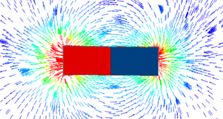
It is helpful to consider a vector diagram for a variety of magnets. We can notice a few consistent behaviors as well as some characteristics unique to each type. We will also observe that magnetic field lines do not intersect, which is an important factor for the ring magnet or any system which uses more than one dipole.
Block
Axial Cylinder
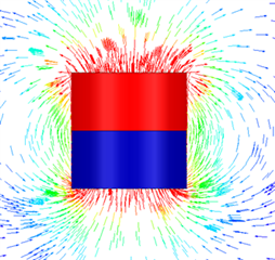
Diametric Cylinder
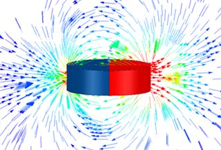
Sphere
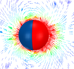
Ring Magnet
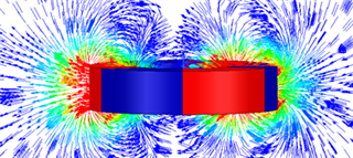
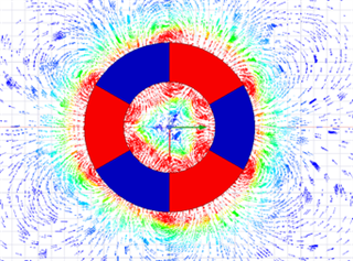
What we can notice immediately is that there are corner effects that are apparent which result in higher magnetic flux density, or B-Field, near the edges and vertices of the magnets. In the case of the sphere where we have no edges, this does not occur and the field is more uniform. As a result, there is often a peak in the magnitude of magnetic flux density near these points. This effect does diminish the further the sensor is from the magnet, however.
Also, it is helpful to remember that the direction of the B-field vector will directly impact the visibility of the field to the sensor. While some locations produce a field parallel to the sensing element, a simple intentional shift in placement can often change the vector direction. Given mechanical constraints don’t always allow this, it is important to remember that various package orientations are available as well as selections of both 2D (TMAG5110, TMAG5111) and 3D sensing options (TMAG5170-Q1, TMAG5273).
How does air gap range impact magnetic flux density?
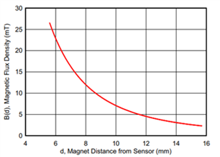
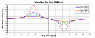
Magnetic flux density is inversely proportional to the square of the distance to the magnet. As a result, there can be a very dramatic change to the field strength as a result of initially small changes in distance. This behavior is important to remember as we are often trying to describe linear travel using this input.
When approaching either pole of the magnet directly in a head on fashion, the field will be entirely in one direction and we might observe variations as shown below
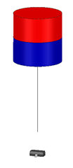
However, there are possible paths that do involve a linear response. Consider a slide-by orientation where a bar or cylinder magnet is drawn past the sensor at a fixed offset.
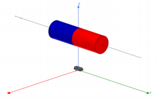
For this motion, there is typically a mostly linear region parallel to the face of the magnet. We can see however, that this field becomes non-linear and the edge effects more pronounced the closer the magnet is to the sensor. For instance, the plot below shows the horizontal motion of the magnet as it travels parallel to the Y axis above. The various lines represent different vertical gaps in the z-direciton.
How does magnet material impact magnetic flux density?
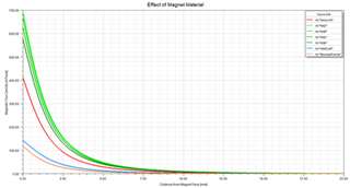
Stronger materials have an observable effect further from the magnet and produce higher magnetic flux density. In the case of the head on approach with a block magnet we can see the difference that various magnetic materials would have in with the same geometry.
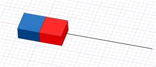
Below we see NdFeB type magnets in green, SmCo18 in red, AlNiCo8 in blue, and a Bonded Ferrite in Orange. Each magnet has the same physical dimensions (3mmx5mmx10mm), and only the magnetic material is changed.
How does magnet size impact magnetic flux density?
Consider the plot below showing the difference in B-Field strength over the range of distances from the face of the magnet. Here we will vary the size of the magnet SmCo18 magnet from the previous simulation by a scale factor ranging from 1 to 5. All dimensions are scaled by the same multiplier. We can observe a few interesting behaviors.
Most importantly, we see that there is more observable field at any distance the larger the magnet is. This is what is intuitively expected. As a general guideline, if a magnet produces insufficient field to reach the threshold of a specific sensor, using a larger magnet will normally help provide greater magnitude B-field as an input. However, it is important to remember that the field will curve around the magnet, and a change in size may result with a vector pointed in a somewhat different direction. Any change in the vector direction will impact the measurement in any Hall effect sensor.
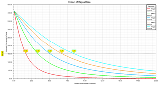
Additionally, the surface field at the center of the polarized face was nearly constant. Increases in the direction of polarization will produce a small increase to the surface field, but typically changing the shape of a magnet tends to have a greater impact on the surface field. In this example the relative dimensions of the magnet are fixed and we have a constant remanence (BR) and coercivity(HC), and so this behavior is normal.
Lastly, for the case where all the dimensions scaled equally, the distance from the magnet required to observe a specific field will also scale by approximately the same factor. Notice that 150 mT is observed at increments of 1.69 mm as the magnet scales.
Are there any other factors which I should consider for my magnet?
Of particular interest in any design is cost. Higher grade magnets and larger magnets tend to be more expensive. Additionally, custom magnets which include multiple poles require bonding or sintering to create the final product. These processes can be difficult and may limit the maximum strength which might be achieved. So, while a stronger magnet may be observed at a greater distance, it might also become cost prohibitive. It may be more ideal to change the magnet shape or orientation to achieve a larger input to the sensor.
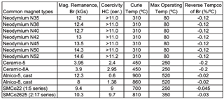
Additionally, temperature drift of the magnet is important as well. For any magnetic material the strength of the magnet will weaken as it heats. The typical drift for each magnet type is shown in the table below
For more guidance related to Hall effect sensors please visit our forum and our video training series available at the links below:

