This thread has been locked.

If you have a related question, please click the "Ask a related question" button in the top right corner. The newly created question will be automatically linked to this question.

TDC1000: ERROR FLAG says no signal

Part Number: TDC1000
Other Parts Discussed in Thread: TUSS4470, PGA460, TUSS4440

Hi There,

I am trying to get the TDC1000 up an running but only get 0x02 as error from register 0x07. The clock is set to 8 MHz. CLK_DIV = 256.

I configure the TDC1000 as follows:

void initTDC1000(){

	HAL_GPIO_WritePin(GPIOB, TDC_RESET_Pin, GPIO_PIN_SET);
	HAL_Delay(250);
	HAL_GPIO_WritePin(GPIOB, TDC_RESET_Pin, GPIO_PIN_RESET);

	// Enable Oscillator
	HAL_GPIO_WritePin(TDC_OSC_ENABLE_GPIO_Port, TDC_OSC_ENABLE_Pin, GPIO_PIN_SET);

	writeToRegister( CONFIG_0, TX_FREQ_DIV_BY_256 );
	writeToRegister( CONFIG_2, TOF_MEAS_MODE_1 );
	writeToRegister( TOF_1, LNA_FB_RESISTIVE | PGA_GAIN_21dB );

	HAL_Delay(100); // Wait for 100 ms

	// Enable TDC1000
	HAL_GPIO_WritePin(GPIOA, TDC_ENABLE_Pin, GPIO_PIN_SET);

}

I checked the registers after setting them and they match with what I want them to be.

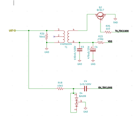
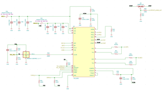
My Schematic looks as follows. I omitted any filtering for now as for now I only need to show that it works.

The signal on the transducer looks like the following

The transducers I'd like to use run on around 40 kHz and look like below:

Would be great if someone could lend me a hand.

Kind regards

  • Hello Andre,

    Thanks for your post to the forum. The scope capture that you are showing above is that probing directly the TX output to the transducer or the TX pin off of the TDC1000?

    I didn't see a channel select write as well so just make sure you are probing the right channel where the signal will be generated. I also noted to value for NUM_TX being written, this tells the TDC1000 device how many pulses to actually transmit, if the number is 0 then the device will not generate any output pulses, the default should be 5.

    There are a couple of reasons you might not be receiving a signal:

    1) The main issue that I noticed for this setup is that you mentioned you are using an 8MHz transducer and using a CLK_DIV = 256 with a 40kHz transducer. The reason this is a problem is because your 8MHz clock needs to be divided to equal your transducers resonant frequency 8MHz/CLK_DIV = 40kHz, you are currently setup to transmit at 31.25kHz. Which means you wont transmit anything and so you will not be able to transmit anything as well. So using a differently clock to divide accordingly should help this problem.

    2) The listening window for the TDC1000 might not be configured correctly. If the listening window is not configured to listen at the appropriate time then you are also likely to receive this error. You can read about this in section 8.4.6 of the datasheet.

    On another note, we typically recommend the TDC1000 to be used with transducer frequencies in the range of 1MHz. The TDC1000 performs best in water coupled applications. If you are working with air coupled applications then I suggest you look at the TUSS4470, TUSS4440, or the PGA460.

    Best,

    Isaac

  • Hi Isaac Lara,

    Thank you very much for your comment, I would like to use this IC as the distance I need to measure is only a couple of cm.

    As you mentioned, I indeed set the TX pulses to zero while I was trying to set the TX Frequency. Anyway I managed to get make it transmit a wave. I currently use a generated CLK of 80 kHz to and divide by 2.

    I also added a booster stage to zap it with more voltage:

    Here an snapshot from a transmission. Blue measures START signal from TDC1000, Yellow measures transducer voltage.

    My problem now is that I can send but I can't see any echoes. Any idea what that might be? I put another transducer opposite the one connected to the TDC1000 and probed it and a wave was clearly visible.

    Cheers

  • Hello Andre,

    Glad to see that you are finally able to transmit the pulses appropriately. Your ultrasonic pulse train transmission looks good and the STOP signal is being generated so that is also a good sign.

    To answer the question about your problem above, the reason you might not be seeing a return signal on the transducer in which you emitted the signal from but are seeing one from the opposite transducer is because the signal is very small when it returns to the originating transducer. The path that the ultrasonic signal has to take is larger than the path in which you placed the other transducer. By the time it arrives at the originating transducer it has attenuated further so a better place to probe for incoming signal would be past the gain stages in your system so if you can probe the COMPIN signal, which is after the LNA and PGA portions of the device. This should give you the additional gain needed to see the signal. But remember if your listening window is not set correctly, the comparator will not engage so you will not see any signal. Also, make sure to have something to have the signal bounce off of and reflect back to the originating transducer if there is not an object then the signal will not return to the transducer. I hope this helps!

    Best,

    Isaac

  • Hi Isaac,

    I will change my filters a bit and check my settings. I'll get back to you as soon as I know more.

  • Andre,

    Sounds good, I hope it works for you.

    Best,

    Isaac