This thread has been locked.

If you have a related question, please click the "Ask a related question" button in the top right corner. The newly created question will be automatically linked to this question.

LDC0851EVM: sensing design for big target

Part Number: LDC0851EVM
Other Parts Discussed in Thread: LDC0851

Thank you very much for your help.
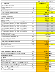
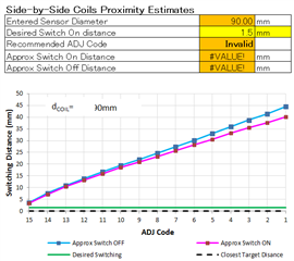
In the design of the LDC0851 sensor, I would like to make the detection width of the detected object 90mm or more.
Please let me know how to achieve this.

By the way, what we are thinking now is
(1) To increase the magnetic field to the detected object, the diameter of the sensor coil should be 90mm or more.
2) To increase the magnetic flux to the detected object, increase the number of coil turns as much as possible.

Please let me know if you have any suggestions.

Translated with www.DeepL.com/Translator (free version)

  • Hiroaki,

    You can use the LDC coil design tool.
    Start with the Spiral_Inductor_Designer tab and select the LDC0851 as the device.
    Input the desired design parameters like coil width = 90mm, the target distance, and the desired number of turns.
    The tool will tell you if the entered parameters result in an fres that is too high or too low.
    You may have to experiment with trade-offs in the coil parameters to get a design that will work.

    Once the coil is designed, you can then move to the LDC0851_calc tab and optimize the design by substituting the coil and distance parameters into that tab's fields.
    It will give you additional information on the capacitor that is needed, and when the device will switch due to the target.

    I hope this helps.
    Please let me know if you have any questions.

    Regards,
    John

  • Thank you for contacting us.
    I am getting the following calculation results from the LDC coil design tool.
    The resistance value Rp is 131.22Ω. Is this value too high?
    What is the recommended value?

    Also, in LDC0851_CALC, when I assign the parameters of the coil and distance to the field
    The optimized value is shown in the orange frame.
    Is the optimized value displayed in the orange frame? I don't know what the optimal value is, but please let me know the recommended value.

    When I use LDC0851_CALC, does it mean that I can use it as a sensor if the black line drawn on the impedance-sensor frequency graph is in the green zone?

    Thank you very much for your help.

  • Hiroaki,

    The Rp of 131.22k in your top table may be okay. You will just have to adjust Idrive so the signal is not too big.

    Your table (from the LDC0851_calc tab) may need to be updated with values from the Spiral_Inductor_Designer tab.
    For example, the sensor inductance shown in your first table is 50.53uH, but the entry in your lower table the inductance is entered as 4.14uH.
    The capacitances and dimensions should be updated as well.

    You are correct about the black line. It should be in the green zone.
    Hopefully updating the parameters will make the line move to the green zone.

    Just so you know, Monday is a holiday in the US, so answers may be delayed.

    Regards,
    John

  • Mr. John.

    Thank you very much for your help.
    Based on your suggestion, I updated the table in the LDC0851_calc tab with Spiral_Inductor_designer's
    I have updated the table in the LDC0851_calc tab with the values from Spiral_Inductor_designer.
    Free Space Sensor Characteristics
    Sensor Indcutance ← D195
    External Sensor Capacitance (Csensor) ← D22
    Parastic PCB Capacitance (Cboard) ← D52

    Sensor Characteristics with Target Interaction
    Sensor Diameter ← D29
    Closest Target Distance ← 0.05 (appropriate value)

    The result is shown in the graph below. Is there any problem with this?

    In particular, in the upper right corner of the Inductance-Sensor frequency graph
    Csensor < 33pf, but
    The D24 of Spiral_inductor_designer is 80PF, and it doesn't seem to match the condition above the Inductance-Sensor frequency graph.
    Is there a problem?

    Also, what is the input point for [Side-by-side coils Proximity Estimates]?
    We have two spiral coils (top: SENCE coil, bottom: SENCE coil).

    We want to use two spiral coils (upper side: SENCE coil, lower side: LREF coil) in two layers.
    We would like to use two spiral coils (upper: SENCE coil, lower: LREF coil) in two layers.
    Is it unnecessary to specify the distance between layers here?
    Do I need to specify the distance between layers here? I entered Disired Switch On distance ← D39, but
    I entered Recommended Adj code, Approx Switch on distance and
    Is there any problem with this?
    Is there any problem?←

    If there are no problems, I will try to make a prototype sensor coil using the inductor coil and capacitor specifications specified in Spiral_inductor_designer.
    If there is no problem, I will try to make a prototype sensor coil using the inductor and capacitor specifications specified in Spiral_inductor_designer.

    Thank you very much for your cooperation.

  • Hiroaki,

    Apologies for the delayed reply. 
    Monday was a holiday in the US.

    The upper-right region representing Csensor < 33pF should be avoided. In other words, Csensor must be > 33pF.
    So a Csensor = 80pF is okay as long as it is combined with the an Lsensor that gives desired operation.
    This is discussed in a little more detail in the data sheet section Sensor Design, section 9.1.1,

    The design approach using side-by-side coils is okay and is shown in data sheet Figure 17, in the section Basic Operation Mode,  8.3.1. It is advised to place the reference target at a distance less than 40% of the coil diameter from the reference coil.

    The case of sense and reference coils using a single target is also covered in the data sheet section 8.3.1, with the advice to make Lref 0.4% less than sense inductance to give the maximum switching distance. 

    The case of stacked coils is covered in some detail in data sheet section Threshold Adjust Mode, 8.3.2, with the comment that it can be used in coarse proximity detection and button applications. To get the most sensing range, it is recommended to separate the sense and reference coils as much as possible (see Figure 1). 

    The cell Recommended ADJ Code is a tool output, not an input, and is related to the cells Closest Target Distance and Desired Switch ON Distance.  All orange cells are tool output fields, not tool input fields. That is why you saw an error. 

    Regards,
    John