Thank you very much for your help.
I am afraid that I have not received any answer to the inquiry I sent earlier, but I would like to give priority to this answer.
★I made an inductor coil for LDC0851EVM and conducted an experiment, but the output of object detection did not turn on from LDC0851EVM.
Photo 1 shows the sensor coil connected between LSENSE and LCOM.
Photo 2 shows a reference coil connected between LCOM and LREF.
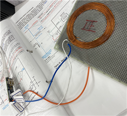
phot1
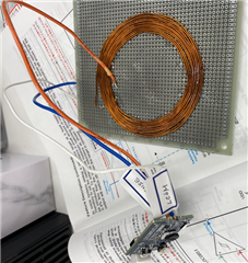
phot2
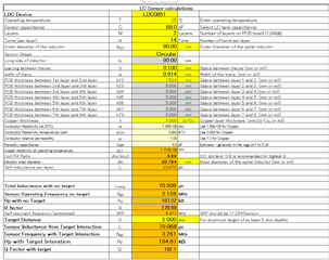
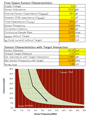
The production conditions of each coil are based on the calculation of spiral inductor and design.
LDC0851_calc.
What I'm thinking now is whether the LC oscillation circuit is working properly or not.
LDC Differential Inductive Switching_Data Sheet, Section 7.7
All we need to do now is to confirm that the LC oscillator circuit is working properly, and that LREF and LSENSE work as described in the timing requirements in the LDC Differential Inductive Switching_Data Sheet, Section 7.7.
All you need to do is to check that the LC oscillator circuit is working properly and that LREF and LSENSE are working as described in LDC Differential Inductive Switching_Data Sheet, Section 7.7 Timing Requirements.