This thread has been locked.

If you have a related question, please click the "Ask a related question" button in the top right corner. The newly created question will be automatically linked to this question.

LDC1614: low power management

Part Number: LDC1614
Other Parts Discussed in Thread: LDC3114-Q1, LDC3114,

Hello, 

We use LDC1614 on our own board to detect the approach of metal on our coil.

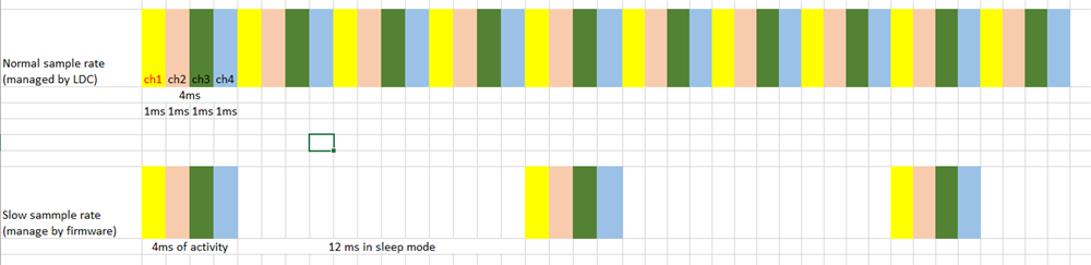
To optimize the energy consumption, we would like to slow down the sample rate (62.5sps) when there is nothing on the coil and increase it (250sps). We use multi-channel mode (4 channels).

To do this and to avoid changing too many registers' values, we manage it by software.

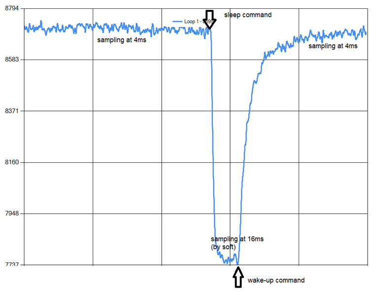
1. we use a timer with 16ms of the period to wake up the LDC1614

2. when DRDY occurs, we read data

3. put LDC1614 into sleep mode, and 16ms later the wake-up command will be executed

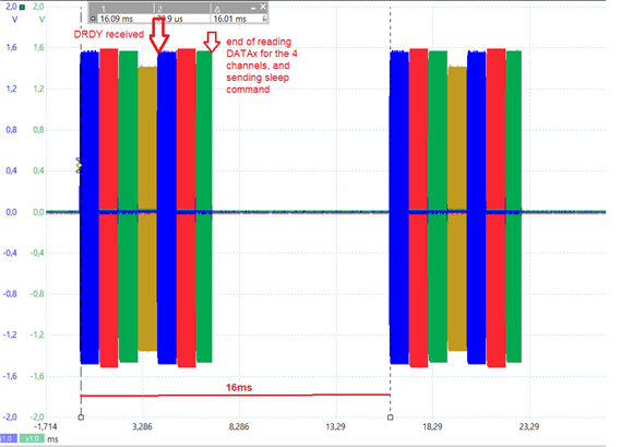
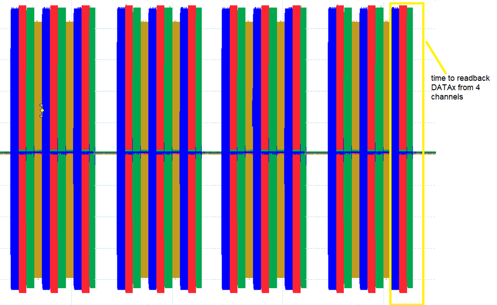
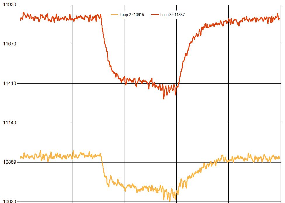
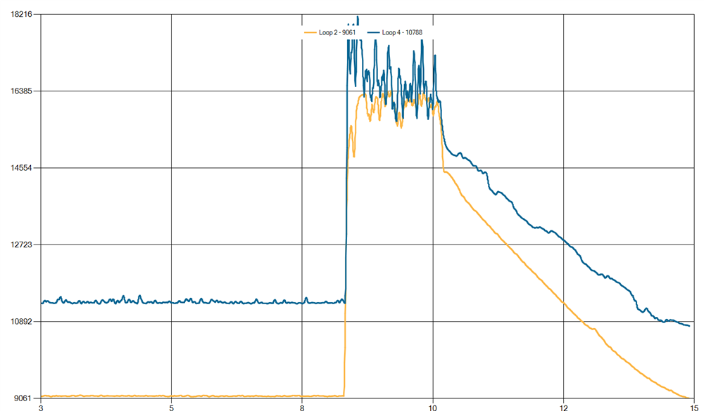
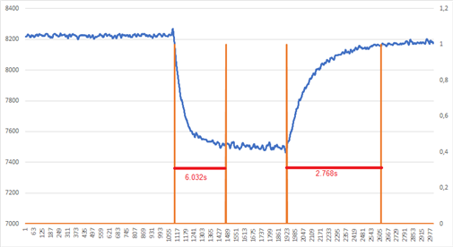
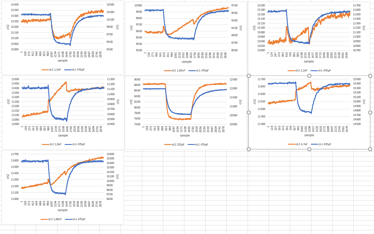
On the graph below, you have in Y-axis the value of DATA.

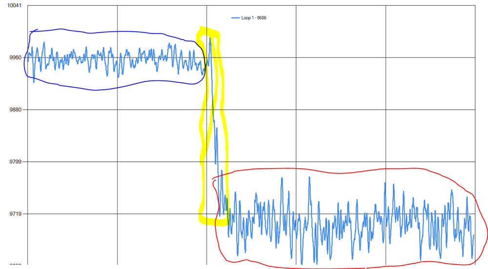
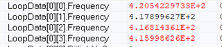
In blue, the part where the sample rate is high.

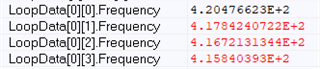
In red, the part where the sample rate was reduced.

In yellow, the transition where an offset appears. We changed nothing except the SLEEP-MODE_EN in CONFIG register.

Do you able to help us to understand how to manage this offset? Is it normal?

And when we speed up the sample rate, the offset appears but in opposite direction (offset is positive) and we arrived at the same amplitude of DATA before the sample rate was slow down.

The problem is, our analysis algorithm detects this amplitude changing as a new detection so some errors occur in our detection.

Thanks a lot for your help.

Kind regards

  • Hello, 

    The LDC1614 does not perform conversions while in sleep mode. In order for the device to take data, it will need to be woken up by changing the SLEEP_MODE_EN bit. Additionally, there is a delay before the first conversion that can be calculated using the following: 16,384÷ƒclk. If you want to sample at a lower sample rate, you can duty cycle the device by waking it up, waiting the activation time, reading the measurement once it is ready, and then sleeping the device again. The Power Reduction Techniques app note has more information on the proper sequence to sleep the LDC between measurements. 

    Best Regards, 

    Justin Beigel

  • Hello, 

    Thanks for your answer,

    Sorry, maybe I am not clear in my explanation. 

    I do not expect to have a conversion during sleep mode. I just need to manage the offset due to a lower sample rate (I think). What is the reason for this offset and how could I manage it?

    I already wait for the activation time (about 4ms) before reading the measurement. I think the problem is not on the sequence of action but on the value that I read on different sample rates that are different and gives some offset on the measurement.

    Kind regards

  • Hello, 

    Thank you for the clarification. I have a question to make sure Based on your initial question,

    We changed nothing except the SLEEP-MODE_EN in CONFIG register

     does this mean that you are leaving the RCOUNT the same for both sampling rates and only changing how often you wake up the device? Can you provide a little more detail on the steps you use to read the data? 

    Thank you, 

    Justin Beigel

  • Hello, 

    Yes, I keep the same value of RCOUNT and SETTLE_COUNT and CLOCK_DIVIDER at the same value, and I sleep and wake up the device by firmware.

    Here below is a picture to describe how it works now. Maybe it is not what I have to do ?

    I use a timer to go to sleep after reading all measurements on 4 channels. I wait for DRDY interruption and after this I read all measurements.

    After the timeout, I wake up the device, and I wait for DRDY IRQ before reading new measurements.

    When I need to have a better resolution, I wake up the device and let the LDC manage the channel shifting, and I read the date each time I received the DRDY IRQ.

    I did not change any parameters except the SLEEP bit.

    RR_SEQUENCE = 2, AUTOSCAN_EN = 1 all the time.

    On the slow sample rate, I analyze each point to wait until something enters to a loop, and when I "guess" that something is present on a loop (by signal's variation), I did not go into sleep to let the LDC have a better resolution. I will go into slow sample rate when I detect that there is nothing on a loop.

    Let me know if you need more detail, and thank you for your assistance

    Kind regards

  • Hello, 

    Thank you for the clarification. Your method of duty cycling the part seems to be correct but I have a few more questions to help determine what the issue is. 

    1. If you read 2 samples each time that you wake up from sleep, is the data consistent between the two samples?
    2. Can you connect an oscilloscope to the sensor and check the oscillation frequency and amplitude for both cases? 
    3. Your graphs appear to be the data code on the Y axis, if you convert this to frequency, how much of a shift is occurring between the two? 
      1. Calculations for this are in the datasheet. This should also be seen and align with measurements taken on the oscilloscope. 

    Thank you, 

    Justin Beigel

  • If I understand well, do you need me to read the same channel twice after receiving a DRDY ? or do you ask me to read a sample without considering DRDY? I will test and let you know the result at the end of the day.

    Thank you

  • Hello, 

    I am asking that you let the EVM perform 2 conversions (per channel) each time you wake it up. Your low sample rate would then change to 8ms of active and 8ms of sleep. I want to see consistency between the first and second sampling for any channel. 

    Best Regards, 

    Justin Beigel

  • Ok, it is clear now, I'll do it and let you know.

    To answer your point 2 : 

    Amplitude are 1.2V-1.6V

    Frequencies are between 418KHz-420KHz (measured using an oscilloscope) for 2 conditions (period = 4ms or 16 ms with sleep mode).

    Do you confirm that to read DATAx value, LDC1614 needs to be in run mode ?  I ask this, because I move a part of my code to go to sleep just at the moment I received the DRDY, and when I read DATAx registers, I got 0 on all channels. If I want to read something from registers, I had to turn LDC1614 into sleep when I finish reading the last channel. But in the meanwhile, a new conversion was already started. See picture below

    I work on point 1 and 3

  • Frequencies measured by firmware using formula in datasheet (in period = 16 ms managed by firmware)

    Frequencies measured (period=4ms)

  • Here below is the result for your point 1.

    I perform 2 conversions before going to sleep.

    And below the evolution of DATAx on 2 channels. I do measurements on 4 channels but just plot 2 channels to see values much clearer.

    The gap is less important than when I have 4ms of measurement and 12 ms of sleep, but it was always present. The amplitude of the signal decrease a little bit when I had 8ms of activity and 8ms of sleep, and go to the initial amplitude when I stay in run mode.


    Is that fit your need? What could we conclude ? 

  • Hello, 

    For your question: 

    Do you confirm that to read DATAx value, LDC1614 needs to be in run mode ?

    Yes, if the device is put into Sleep mode or Shutdown mode, all DATAx_MSB and DATAx_LSB registers are cleared of conversion data. 

    I am still looking into the cause of the offset for you and should have a better update by the end of the week. In the meantime, I do have one more question. Are you using the RP_OVERRIDE_EN or letting the device auto-calibrate the sensor amplitude? 

    Thank you, 

    Justin Beigel

  • Hello, 

    Thanks for your answer.

    Yes, RP_OVERRIDE_EN is set. 

  • I tried to do some tests without activate RP_OVERRRIDE_EN, and I get this result:

    Signal fluctuate a lot even before I change the sample rate. When I reduced the sample rate (using sleep mode and soft timer), the amplitude goes high (DATAx values) and the signal is not stable at all compared to previous behavior. 

    Finally, when I restore the normal sample rate (managed by LDC1614), the signal decrease slowly and goes back to the previous amplitude.

    PS : I will be on vacation from this friday, but I will work on this problem at full time before. So, if you will not have any answer from my side it is just because I am off

  • Hello, 

    Thank you for confirming the RP_OVERRIDE_EN setting. I would leave this as set but there is a chance that a different IDRIVE value will provide more consistent results. If you want to test this, I would start by increasing it slightly since your channel 3 seems to be the lowest around 1.4V amplitude. The concern for increasing it is that your other channels should not go above 1.8V amplitude. 

    Thanks for the heads up on your vacation, we will still work to provide you with an update as quickly as we can. 

    Best Regards, 
    Justin Beigel

  • Hello, 

    Thanks for your answer. I had already test each value of  IDRIVE, but I am not able to find a value that removes the offset. In fact, the offset is reduced sometimes (from 500 to 300) but I was never able to do better. 

    I already try to change the value of RCOUNT and SETTLECOUNT to see the impact of these parameters on the problem, but it was not conclusive.

    Kind regards

  • Do you able to reproduce the problem on your side?

  • Hello, 

    Thank you for the additional information. I am still working to recreate this issue on our side. I will post an update as soon as I have more information. 

    Best Regards, 

    Justin Beigel

  • Hello, 

    I am back from vacation. Is there a new update on our side ? I could do more tests if needed. Let me know if you need anything else.

    I will be able to work on it from tomorrow.

    Thanks a lot for your support

    Kind regards

  • Hello, 

    I am having issue with the setup on my end and there is another test I want to run tomorrow for this. I should have more information by the end of the day tomorrow. 

    In the meantime, if low power is an important part of this application, would a switch to the LDC3114-Q1 device be an option? It has better EMI performance and a built in low power mode that can change the sample rate through register settings. The only concern I see for your application based on the information I have so far is the sensor frequency. This would need to be increased to be within the LDC3114's parameters. 

    Best Regards, 

    Justin Beigel

  • Hello, 

    Thanks for your update. I will have a look on the LDC3114-Q1. Quickly, I saw that the device is not in production yet and the sample rate max is 160SPS. To have the same performance that we offer today, we use the LDC1614 with 250SPS. We also have to check the sensor inductance. Maybe I will order an evaluation board of this new device to test it on our side.

    Kind regards

    Andrianina

  • Hello Andrianina, 

    The LDC3114 also has a continuous operation mode similar to how the LDC1614 operates. There is no RCOUNT setting available that impacts the sampling time, but the timing is dependent on the sensor frequency. 

    Best Regards, 

    Justin Beigel

  • Hi Justin, 

    I order today an evaluation board to test the LDC3114. We will look closely at this alternative.

    But for now, we already have a product based on LDC1614 that is available for our client in non-low power mode and we would like to offer the same performance but in a low power mode (battery-powered). The expected date for marketing is the beginning of 2022. We already do a lot of tests for more than 1 year on the LDC1614 and all of our driver and detection algorithms work well and satisfy our clients. So changing today to the LDC3114 will be difficult for us because we do not evaluate it correctly, and we will have to redo a validation step on it before offering it to our client. I am afraid that we will not meet our plans if we change the device now.

    So, I would like to try to make the LDC1614 work, even, if I have to manage something by software to correct the signal. I hope you understand our situation.

    I will have time tomorrow to work on this problem to try if I found something, but do not hesitate if you need or find something on your side.

    Thanks a lot

    Kind regards

  • Hello Andrianina, 

    I understand your concern with switching. I made progress on my side and was able to create something similar to what you are seeing. I have more testing to do on this though for working on a solution. So far, the best solution I have is to add an offset to the data when duty cycling the device. What is your threshold for triggering the device to go back into normal power? Also, how low does the data code go in normal power mode with your target interaction? 

    Thank you, 

    Justin Beigel

  • Hi Justin, 

    We go back to normal mode after the signal increased during more than 3 points @ 4ms => 12ms. The raw data we received is filtered to have a good trend and to limit the number of false detection.

    We could stay in normal mode for less than 4 sec. It is the maximum value ( a timeout). But generally, the duration we stay in normal mode is about 1.5-2 sec. 

    Kind regards

  • Thanks for clarifying. 

    When you first start the device in normal mode, are there any intermediate steps between waking up the LDC and starting to take data samples? If so, do you know how much delay this causes? 

    Also, do you know what the timing of the following is: 

    Thank you, 

    Justin Beigel

  • Hello Justin, 

    No there are not any intermediate steps between waking up LDC and getting data.

    Here below are the duration of each step (High to low = 6 sec and low to high = 2.7 sec).  In X-axis you have the number of samples.

    To remember, the signal stays at "high level" when sampling rate = 4ms, and goes low when sampling rate = 16 ms.

    Changing sampling rate occurs at the beginning of the signal transition (high to low or low to high). Not sure that I am pretty clear but do not hesitate to ask if needed for more explanation.

    Thanks

    Kind regards

  • Thanks for that information. 

    Would you be able to share a full register dump? I am mainly wanting to look at the deglitch filter setting, Idrive setting value, and config register value. But having the full register values would be helpful incase anything else is needed. 

    Also, with your oscilloscope, can you zoom in on the starting portion of channel 0's oscillation? Something like this: 

    Based on your current screenshots, I don't think there will be an issue here. I just want to verify it is matching the register settings. 

    Thank you, 

    Justin Beigel

  • Hi Justin, 

    My bad, I should have sent it to you earlier. Here below all my registers values :

        0x05C3,     //!< Rcount0         :  Reference Count setting for Channel 0 : 590µs
        0x05C3,     //!< Rcount1         :  Reference Count setting for Channel 1 : 590µs
        0x05C3,     //!< Rcount2         :  Reference Count setting for Channel 2 : 590µs
        0x05C3,     //!< Rcount3         :  Reference Count setting for Channel 3 : 590µs
        0x0000,     //!< Offset0         :  Offset value for Channel 0
        0x0000,     //!< Offset1         :  Offset value for Channel 1
        0x0000,     //!< Offset2         :  Offset value for Channel 2
        0x0000,     //!< Offset3         :  Offset value for Channel 3
        0x0400,     //!< Settlecount0    :  Channel 0 Settling Reference Count : 410µs
        0x0400,     //!< Settlecount1    :  Channel 1 Settling Reference Count : 410µs
        0x0400,     //!< Settlecount2    :  Channel 2 Settling Reference Count : 410µs
        0x0400,     //!< Settlecount3    :  Channel 3 Settling Reference Count : 410µs
        LDC_SET_FIN_DIV(1) | LDC_SET_FREF_DIV(1),        //!< ClockDividers0  :  Reference and Sensor Divider settings for Channel 0
        LDC_SET_FIN_DIV(1) | LDC_SET_FREF_DIV(1),        //!< ClockDividers1  :  Reference and Sensor Divider settings for Channel 1
        LDC_SET_FIN_DIV(1) | LDC_SET_FREF_DIV(1),        //!< ClockDividers2  :  Reference and Sensor Divider settings for Channel 2
        LDC_SET_FIN_DIV(1) | LDC_SET_FREF_DIV(1),        //!< ClockDividers3  :  Reference and Sensor Divider settings for Channel 3
        0,                                                      //!< Status          :  Device Status Report
            LDC_SET_DRDY_2INT,                                  //!< ErrorConfig : Error Reporting Configuration
        LDC_SET_RP_OVERRIDE_EN | LDC_SET_SENSOR_ACTIVATE_SEL |
            LDC_SET_AUTO_AMP_DIS | LDC_SET_REF_CLK_SRC |
            LDC13xx16xx_BIT_SLEEP,                              //!< Config      : Conversion Configuration
        LDC_SET_AUTOSCAN_EN | LDC_SET_RR_SEQUENCE(2) |
            LDC_SET_DEGLITCH(1) | LDC_SET_RESERVED(65),         //!< MuxConfig : Channel Multiplexing Configuration (increase deglitch filter improve the loop's freq computation
        LDC_SET_RESET_DEV,                                      //!< ResetDev        :  Reset Device
        0x0200,                 //!< This value is not documented into datasheet. Keeping default value is recommanded
        LDC_SET_IDRIVE(16),     //!< DriveCurrent0   :  Channel 0 sensor current drive configuration
        LDC_SET_IDRIVE(16),     //!< DriveCurrent1   :  Channel 1 sensor current drive configuration
        LDC_SET_IDRIVE(16),     //!< DriveCurrent2   :  Channel 2 sensor current drive configuration
        LDC_SET_IDRIVE(16),     //!< DriveCurrent3   :  Channel 3 sensor current drive configuration

    IDRIVE = 16

    DEGLITCH FILTER = 1, and already tried all values of deglitch filter but no improvement in my case

    FREF = 40MHz

    CONFIG = 0x1E00 (SLEEP_MODE_EN bit is driven by code regarding differents steps of product : initialisation, normal mode or low power mode with slower sampling rate)

    Kind regards

    Andrianina

  • Hello Andrianina, 

    Thanks for the information. This shouldn't make a difference but the CONFIG register has the reserved bit at the end that should be written to 1. 

    It is a small change and shouldn't have an impact but I would recommend updating to write 0x1E01 instead. 

    For the difference in data, I was able to get a consistent data in both duty cycle and non by tweaking the Idrive setting for my sensor. I know you want a pure software fix, but for the sake of testing, would you be able to change the capacitor on one of your sensors to see if an Idrive setting change would provide better results? 

    Thank you, 

    Justin Beigel

  • Hi Justin, 

    I will add the reserved's CONFIG bit, thank you.

    Could you give me the value of your inductance and your capacitor just to have an idea of what range of capacitors I may use for my test, please?

    My inductance is 150µH, and my capacitor is 470pF. I will begin some tests this afternoon by decrease the value of my capacitor and let you know.

    Thanks

    Kind regards

    Andrianina

  • Hello Andrianina, 

    I am using the sensor that is on the LDC1614EVM CH0 and CH1. This is a 21uH inductor with a 330pF capacitor. 

    For your change in capacitance, a 290pF capacitor should be plenty of change. You can do other steps in between as well and you can even go lower if you want but that should be sufficient to see change. 

    Best Regards, 

    Justin Beigel

  • Hi Justin, 

    I did some tests yesterday. In the attached file are the details of all values (in xlsx format), but below is a picture to summarize all cases.

    To be clear, for each graph, the first part of the signal is at a 4ms sampling rate, followed by a 16ms sampling rate, and finished with a return to 4ms.

    Loop inductance = 150µH

    Idrive = 16 (register value). I tried different values of Idrive but the impact is very limited (sometimes imperceptible). With the idrive's value of 16, the signal amplitude is around 1.3V.

    Only the capacitor on channel 2 (loop #2) was changed. Channel 1 is still unchanged with the default value (470pF) to compare the impact.

    From what I see, 1.68nF is the least bad of all cases. After these tests, I still have trouble understanding the relationship between the capacitance (loop oscillation) and the offset that we see when we change de sampling rate. Maybe these measurements may help you to understand something. Do not hesitate if you need more details.

    Kind regards

    recap.xlsx

  • Hello, 

    Thank you for the additional information. I need to do more testing on my end but will have an update for you by the end of the week. 

    Best Regards, 

    Justin Beigel

  • Hello Justin, 

    On my side, I put this subject on hold for your feedback. Let me know if you need more information to move forward. Thank you.

    Kind regards

  • Hello, 

    I just sent you a direct message to further discuss testing. 

    Best Regards, 

    Justin Beigel

  • Hello, 

    Following your recommendation, I changed progressively the value of the capacitor from 470pF to 10pF, and I didn't see any good result. I still have the offset when I change the sampling rate. Until this day, and from my previous test, the only value that gives us the least bad result is with the 1.68nF capacitor.

    Unless you have another idea, I think I will do some more tests with this value of the capacitor to confirm if this value is good for our application. I will manage by software the little glitch that I have. I need to do some more tests to be sure that it is ok in all conditions. I will let you know my results.

    Do not hesitate if you have another recommendation that I can check on my side.

    Thanks a lot

    Kind regards

  • Hello, 

    We don't have any other suggestions on this at this time. Let us know if the additional tests and software management is not enough to solve this issue. I am going to close this thread for now but feel free to respond here if you have any more related questions. 

    Best Regards, 

    Justin Beigel